Skip to content
 Press fits—also known as interference fits—are a foundational joining technique in engineering and manufacturing. They enable two components, typically a shaft and a hole, to be joined securely without welding, adhesives, or fasteners. The key to a successful press fit lies in tolerance control—ensuring just the right amount of interference for strength without risking deformation or assembly failure.
In this guide, we’ll explain what press fits are, how tolerance plays a critical role, and how to properly design press fit components for performance and reliability.
What Is a Press Fit?
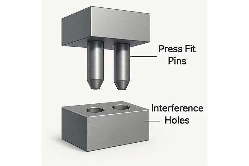
In high-precision manufacturing, securing components without adhesives or fasteners can be a challenge.
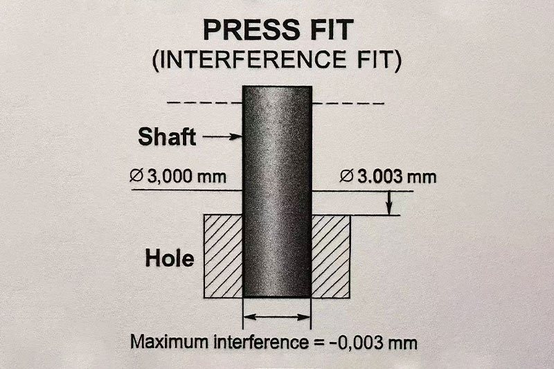
A press fit is a mechanical fastening method where one component is slightly larger than the mating part, creating a tight fit through interference. This method is common in applications requiring secure, immobile joints without secondary fasteners.
Let’s dive deeper into what makes press fits functionally reliable and how they’re applied effectively in real-world engineering.
How Does a Press Fit Work?
The goal is to create a frictional bond between two mating parts, usually a shaft and a hole.
Press fits work by intentionally sizing the shaft slightly larger than the hole. This requires one component to be pressed into the other, which generates radial stress. The result is a tight connection that doesn’t rely on additional fasteners or adhesives.
Elastic vs. Plastic Deformation
During a proper press fit:
- Elastic deformation occurs within material limits, allowing reusability.
- Plastic deformation may happen in tighter fits, creating a permanent bond.
Benefits of Press Fits
| Advantage | Description |
|---|---|
| Fast Assembly | Reduces or eliminates the need for screws, rivets, or adhesives. |
| Strong Hold | Provides excellent retention even under vibration and dynamic loads. |
| Space-Saving | Ideal for compact designs where hardware clearance is minimal. |
Common Applications
- Electric motor rotors and bushings
- Gear and pulley mounting
- Automotive axle and bearing installations
- Medical device housing alignment

Important Considerations
For a successful press fit, you must consider:
- Material strength and hardness
- Thermal expansion differences
- Surface finishes and lubrication
- Assembly method (cold press, thermal, vibration-assisted)
Ultimately, a press fit’s reliability hinges on proper design and tolerance control. By understanding these fundamentals, you can integrate press fits confidently into your engineering assemblies.
The Role of Tolerance in Press Fits
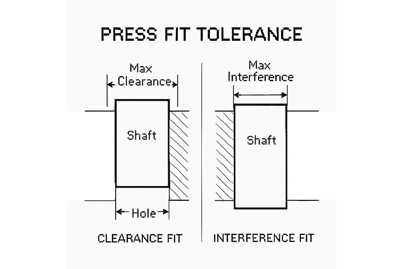
Tight, reliable assembly matters—but too tight, and parts break. Too loose, and they slip. That’s where tolerance becomes critical.
In press fit assemblies, tolerance defines how much interference exists between the shaft and the hole. This precision is what governs the fit’s strength, durability, and manufacturability.
Tolerance in press fits refers to the allowable dimensional variation in both components that results in a predictable level of interference. This balance ensures consistent performance under real-world loads and conditions.

Why Tolerance Matters
| Factor | Effect of Tolerance |
|---|---|
| Holding Strength | Tighter interference increases friction and retention force. |
| Assembly Effort | Looser fits assemble easily but may compromise durability. |
| Deformation Risk | Overly tight fits can crack or distort thin-walled components. |
| Component Longevity | Improper fits can wear prematurely under cyclic or thermal loading. |
Key Concepts in Press Fit Tolerance
- Nominal Size: The ideal diameter of both components (e.g., Ø20.00 mm).
- Tolerance Band: The allowable variation from the nominal (e.g., +0.014 / -0.000 mm).
- Interference Range: The overlapping area where the shaft is larger than the hole.
Design Balance
A well-designed press fit is a compromise. Designers must:
- Allow just enough interference for the required holding force
- Minimize stress on mating parts to prevent damage
- Ensure repeatability across production batches and materials
These goals are often achieved through standard ISO fit systems (like H7/p6 or H7/m6), which combine proven hole and shaft tolerance values for reliable performance.
In summary, understanding and controlling press fit tolerances isn’t just a design preference—it’s a requirement for durable, high-performance assemblies.
Common Press Fit Tolerance Combinations (ISO System)
Choosing the right tolerance combination is crucial for a successful press fit. ISO 286 provides a standardized system for matching shafts and holes using tolerance symbols. These symbols indicate the permissible dimensional variation for each component—and thus determine the level of interference.
The hole is typically assigned an H7 tolerance, which means it has a zero lower deviation and a small positive upper deviation. The shaft tolerances—k6, m6, p6, and s6—represent increasing levels of interference.
ISO Press Fit Tolerance Guide
| Fit Type | Hole Tolerance | Shaft Tolerance | Typical Applications |
|---|---|---|---|
| Light Press Fit | H7 | k6 | Bearings, pins in soft materials |
| Medium Press Fit | H7 | m6 | Gear mounting, pulleys, moderate stress parts |
| Heavy Press Fit | H7 | p6 or s6 | High-load structures, motor rotors, permanent fits |

Understanding Tolerance Effects
- H7: A standard hole tolerance with no lower deviation, ensuring all fits are interference-based.
- k6: Creates a minimal interference suitable for easy press fit assemblies.
- m6: Offers moderate interference for reliable holding power without excessive stress.
- p6 / s6: Provide tight interference; best for components that require rigid locking and won’t be disassembled.
Always match your fit selection with your material properties and expected operating conditions. For high-precision applications or critical joints, use simulation or tolerance analysis to validate fit integrity under real-world loads and temperatures.
Example: Press Fit Tolerance for a Ø20 mm Shaft
To illustrate how ISO press fit tolerances work in practice, let’s take a 20 mm nominal diameter shaft as an example. By applying standard H7 hole tolerances and various shaft fits—k6, m6, and p6—we can calculate the exact interference range.
The table below shows the allowable dimensional ranges for each combination and the resulting interference in microns (µm):
20 mm Shaft Press Fit Tolerance Comparison
| Fit | Hole Tolerance (H7) | Shaft Tolerance | Resulting Interference |
|---|---|---|---|
| H7/k6 | 20.000–20.018 mm | 20.009–20.025 mm | 9 to 25 µm |
| H7/m6 | 20.000–20.018 mm | 20.014–20.030 mm | 14 to 30 µm |
| H7/p6 | 20.000–20.018 mm | 20.020–20.037 mm | 20 to 37 µm |
Interpreting the Results
- H7/k6: Best for light-duty press fits where easy assembly and moderate retention are required.
- H7/m6: Offers stronger interference suitable for gears, pulleys, or rotating components that must not slip.
- H7/p6: Delivers a tight, high-holding-strength fit appropriate for permanent structural assemblies or motor cores.

When selecting the fit, consider material compatibility, installation methods, and load conditions. Overly tight fits can cause stress fractures or deformation, especially in soft metals or thin-walled parts.
Methods for Assembling Press Fits
Assembling press fits involves overcoming the interference between parts without causing damage. The choice of method depends on the part size, material properties, and precision requirements.
Below are the most effective techniques used in industry to install press fit components safely and accurately:
Cold Pressing
- Description: Involves pressing parts together at room temperature using hydraulic or mechanical presses.
- Best For: Small to medium-sized components where tight control of tolerances is feasible.
- Considerations: Excessively tight fits can cause galling (surface tearing) or component deformation, especially if lubrication is not used.
Thermal Assembly
- Shrink Fit: The inner component (shaft) is cooled—often with liquid nitrogen—causing it to contract before insertion.
- Expansion Fit: The outer component (hole or housing) is heated, expanding its diameter to allow easier assembly.
- Benefits: Reduces insertion force, minimizes risk of surface damage, and allows tighter fits than cold pressing.
- Applications: Frequently used in electric motor assemblies, bearing seats, and aerospace components.

Ultrasonic or Vibration-Assisted Pressing
- Description: Applies ultrasonic energy or high-frequency vibrations during the press fit process to reduce friction and insertion force.
- Advantages: Significantly lowers heat generation, enhances alignment, and minimizes damage to delicate surfaces.
- Use Cases: Ideal for precision plastic parts, small-scale electronics, or assemblies involving dissimilar materials with varying hardness.
Each assembly method has distinct pros and cons. The right choice ensures both part integrity and assembly efficiency, especially for high-volume or mission-critical applications.
Factors Affecting Press Fit Tolerance Design
Press fit tolerance isn’t a one-size-fits-all solution. Its success depends heavily on contextual factors, from material properties to expected service conditions. Here’s a breakdown of key considerations that must be factored into the design process.

Material Properties
Softer materials, such as plastics or low-carbon steels, can’t tolerate as much interference as harder metals like tool steel or titanium. Too tight a fit can cause crushing or permanent deformation. Therefore, interference should be minimized for ductile or brittle materials to prevent failure.
Surface Finish
Rough surfaces significantly increase friction during assembly, requiring more force and potentially damaging the mating parts. A controlled surface finish—typically Ra 0.4–1.6 µm—helps balance friction and bonding strength, improving both reliability and ease of insertion.
Part Geometry
Thin-walled components are especially vulnerable to radial stress caused by press fitting. Excessive interference can distort or crack the outer component. It’s critical to analyze wall thickness and support features when deciding on fit tolerance.
Operating Temperature
Press fits must remain secure throughout thermal cycling. If a shaft and housing expand or contract at different rates due to temperature changes, the interference may loosen or tighten undesirably. Materials with matched coefficients of thermal expansion should be prioritized, or thermal effects compensated in the design.
Application Stress
Components under heavy mechanical or rotational loads demand tighter press fits to ensure zero slip between parts. For example, gears transmitting torque or rotors in motors often use heavier interference fits like H7/p6 or H7/s6 to withstand stress without movement.
Reusability
Not all press fits are designed for one-time use. If disassembly is needed, lighter fits (e.g., H7/k6) or alternative joining methods should be considered. Permanent fits, while stronger, can be destructive when disassembled and are less suitable for prototyping or serviceable designs.
Balancing these variables ensures your press fit not only performs as intended but also avoids common pitfalls like galling, slippage, or premature failure.
Tips for Designing Tolerance Press Fits
Effective press fit design is more than just choosing the right tolerance combination—it’s about engineering with foresight. Below are practical tips that help ensure press fits achieve consistent performance, are manufacturable, and minimize assembly risks.
Use ISO Standard Fits
Relying on ISO standard fit combinations like H7/p6 or H7/m6 simplifies design and manufacturing communication. These predefined tolerances ensure consistency across vendors and manufacturing systems, reducing ambiguity in production and inspection.
Avoid Overtight Fits on Thin Components
Thin-walled parts are susceptible to deformation under excessive press force. Instead of tightening interference, consider optimizing wall thickness or using light press fits like H7/k6. Structural reinforcements or fixtures can also help resist deformation during assembly.
Account for Thermal Effects
In applications subject to wide temperature ranges, differential thermal expansion can loosen or overly tighten the fit. Material compatibility and tolerance selection should reflect the component’s thermal environment—especially for rotating machinery or outdoor installations.
Perform Finite Element Analysis (FEA)
For high-load, high-value, or safety-critical components, use FEA to simulate stress distribution and deformation from press fitting. This prevents surprises during prototype testing or field use and validates your tolerance assumptions under realistic conditions.
Use Precision Holes for Consistency
Precision hole-making techniques such as reaming or boring result in tighter control over diameter variation compared to standard drilling. This ensures more predictable press fit interference and reduces assembly variability.
Control Surface Finish
A surface roughness of Ra 0.4–1.6 µm strikes a balance between friction and insertion ease. Too smooth, and the joint may slip; too rough, and insertion forces rise sharply, risking galling or damage. Specify finish on the drawing and confirm during inspection.
Specify Assembly Method
Indicate whether press fit assembly should use mechanical force, thermal expansion, or other specialized techniques. This improves consistency during installation and avoids unintended stress on the parts. For example, note “Thermal fit—outer ring to be heated to 120°C before assembly.”
Include Pre- and Post-Assembly Inspection Points
Define key inspection points both before and after press fitting. This includes component diameters, roundness, and critical concentricity dimensions. Monitoring these ensures both parts were within spec prior to assembly and identifies deformation or slippage post-fit.
When incorporated early into design, these tips drastically improve press fit reliability, streamline assembly, and support long-term durability.
Applications of Press Fit Joints
Press fit joints are foundational to precision engineering across many industries. Their strength, simplicity, and cost-effectiveness make them ideal where welding, adhesives, or threaded fasteners aren’t optimal. Let’s explore their real-world applications.
Automotive
In the automotive industry, press fits are used extensively to ensure secure, vibration-resistant connections. Gear hubs are commonly mounted on shafts via interference fits, providing robust torque transmission without slippage. Crankshaft pulleys and bushings also benefit from press fits, maintaining alignment and power delivery under dynamic loading conditions. These joints are reliable and compact—ideal for the constrained, high-performance environments within modern engines.
Aerospace
Aerospace applications demand lightweight, high-strength, and temperature-resistant connections. Press fits are used for mounting bearing sleeves in housings and aligning rotor components within engines or control systems. Because aerospace materials like titanium and aluminum alloys behave differently under temperature stress, press fits offer a precise, non-welded alternative that simplifies maintenance while retaining structural integrity under extreme loads.
Medical Devices
Precision and cleanliness are critical in the medical sector. Press fits are used to assemble surgical tools where sterilization, biocompatibility, and compact size are essential. Joints between metal shafts and handles or between modular components rely on interference fits to maintain tight tolerances without additional fasteners that could trap contaminants. These joints enable high repeatability and easy sterilization.
Industrial Machinery
Heavy-duty equipment often uses press fits for gears, couplings, and flywheels. In these scenarios, press fits reduce play and ensure accurate alignment, which is crucial for efficient power transfer. They also simplify part replacement and service, as there’s no need to undo bolts or welds. When paired with thermal assembly, large components can be fit precisely without damaging surrounding structures.

Consumer Electronics
Compact and clean aesthetics are vital in electronics, making press fits a natural choice for mounting PCB pins, buttons, and housings. These joints allow for fast, glue-free assembly while maintaining precise alignment. In smartphones and wearables, press fits secure components with minimal space usage and support mass production efficiency. They also enhance product longevity by minimizing vibration-related loosening over time.
Across all these industries, the press fit’s unique blend of strength, simplicity, and scalability proves invaluable in both prototyping and high-volume manufacturing.
Common Press Fit Failures and Their Causes
Despite their effectiveness, press fits can fail if not properly designed or assembled. These failures are often preventable and usually stem from poor tolerance planning, incorrect material choices, or inadequate assembly procedures.
Failure Mode: Loosening During Use
This occurs when the interference fit doesn’t provide sufficient holding force, typically due to an overly loose fit or high thermal variation. Materials expand or contract under temperature changes, and if the coefficient of expansion isn’t accounted for, parts may lose contact. A poor surface finish can also reduce the friction required to hold components together.
Failure Mode: Cracking of the Housing
If the interference is too aggressive—especially in brittle or thin-walled materials—the housing can crack during or after assembly. This often happens when designers specify a tight fit (e.g., H7/p6 or tighter) without considering material strength and wall thickness. Cast components and plastics are particularly susceptible to this kind of damage.
Failure Mode: Galling or Surface Damage
When surface roughness is too high or lubrication is not applied during press fitting, metal-to-metal contact can cause galling. This is a form of adhesive wear where material from one surface transfers to another, leading to scoring, seizing, and eventual mechanical failure. Poor surface finishes (Ra > 1.6 μm) often contribute to this issue.
Failure Mode: Misalignment
Even a perfectly dimensioned press fit can fail if assembly is misaligned. Axial or angular misalignment during insertion can cause uneven stress, bending, or gouging—leading to loss of concentricity or premature loosening. Precision fixturing or guided pressing is essential, especially for long shafts or deep bores.
| Failure Mode | Root Cause |
|---|---|
| Loosening during use | Insufficient interference or thermal expansion mismatch |
| Cracking of the housing | Over-tight fit in brittle or thin-walled material |
| Galling/surface damage | Poor lubrication or high surface roughness |
| Misalignment | Improper axial or angular positioning during assembly |
Understanding these failure modes helps engineers apply appropriate fits, materials, and assembly methods—ultimately enhancing product reliability and lifecycle performance.
Conclusion
Effective press fits combine robust mechanical performance with cost-efficient manufacturing—but only when tolerances, fits, and materials are precisely defined. This isn’t just about dimensioning—it’s about collaboration. Engineers must calculate interference fits with care, machinists must control tolerances with precision, and quality teams must validate assemblies under real-world conditions.
From soft bushing mounts to high-load transmission hubs, the applications of press fits are diverse, but the core principle remains the same: correct fit equals lasting reliability. By aligning design intent with manufacturing feasibility, you prevent costly issues like deformation, misalignment, or part failure.
If you’re working on critical assemblies—whether automotive, aerospace, or electronics—now’s the time to revisit your tolerance strategy. Use ISO fit tables, model thermal effects, and define surface finish standards. The more intentional your press fit design, the more durable and consistent your product performance will be.