Skip to content
 Computer Numerical Control (CNC) lathes are the backbone of modern manufacturing—offering unmatched speed, precision, and repeatability for turning operations. Whether you’re producing complex aerospace fittings or high-volume automotive shafts, understanding the essential components of a CNC lathe is key to optimizing performance, maintaining accuracy, and reducing downtime.
This guide breaks down the 9 core components of a CNC lathe—each one critical to part quality and machine reliability.
Headstock: What Makes It the Heart of CNC Lathe Operation?
Precision turning starts with stability—and that begins at the headstock. If this key component isn’t right, nothing else will be.
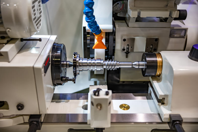
The headstock on a CNC lathe houses the main spindle and the motor or gearbox that drives it. It ensures the rotation of the workpiece is concentric, balanced, and stable during machining.
Why the Headstock Matters
The headstock sits at the left end of the machine and plays a pivotal role in both power transmission and structural rigidity. It absorbs the reactive forces generated during high-speed cutting and ensures the part spins consistently without wobble. A well-designed headstock guarantees that even under stress, the spindle remains in perfect alignment—a necessity for dimensional accuracy and repeatability.
Types of Headstock Configurations
| Headstock Type | Description | Best For |
|---|---|---|
| Fixed Headstock | Spindle remains in a fixed position; ideal for larger parts | Standard turning operations |
| Sliding Headstock | Spindle moves along Z-axis; commonly found in Swiss-type lathes | Small, long, high-precision parts |
Critical Design Features
- Spindle bearings: Precision bearings ensure minimal runout and high rigidity.
- Motor integration: Some use belt drives; others have direct-drive motors for enhanced torque and speed control.
- Cooling systems: Integrated coolant passages protect against heat buildup during continuous cutting.
- Enclosure design: Modern headstocks are enclosed for chip and coolant management, as well as noise reduction.
My Experience on the Shop Floor
One of our aerospace clients struggled with inconsistent turning results on long titanium shafts. After inspecting the setup, we discovered their headstock had excessive thermal drift due to inadequate cooling around the spindle motor. We switched them to a headstock design with active liquid cooling and ceramic hybrid bearings. The result? A 38% improvement in roundness and a dramatic reduction in post-processing time.
Key Takeaway
If your parts are showing signs of vibration, dimensional variation, or poor surface finish, the headstock could be your root cause. Don’t underestimate this component—invest in rigidity, temperature control, and proper motor-spindle integration to ensure your CNC lathe runs at peak precision.
A rigid, high-speed headstock ensures stable turning and improved surface finish—especially during high-RPM cutting.
Spindle: How Does It Drive CNC Lathe Precision?
If the headstock is the heart of a CNC lathe, the spindle is its pulse—delivering motion, power, and precision in every rotation.
The spindle is a rotating shaft located inside the headstock that drives the workpiece or cutting tool. It is the primary mechanism for delivering torque and rotational motion in turning operations.
Understanding Spindle Functionality
Every cut begins with spindle rotation. The spindle’s job is to hold the workpiece securely—via a chuck, collet, or fixture—and spin it with consistent velocity while resisting radial and axial cutting forces. A well-designed spindle ensures the tool meets the material with precision, stability, and the exact amount of force needed to produce flawless results.
Types of CNC Lathe Spindles
| Spindle Type | Description | Ideal For |
|---|---|---|
| Belt-Driven | Motor and spindle are connected via a belt | General-purpose applications with lower RPM demands |
| Gear-Driven | Uses gears for torque transmission | Heavy-duty machining requiring high torque |
| Direct-Drive | Motor is integrated directly with the spindle | High-speed, high-precision operations (medical, optics) |
Performance Metrics to Watch
- Runout: Indicates how much the spindle deviates from its true center—critical for tight-tolerance parts.
- Torque and Power Ratings: Determine how aggressively you can cut and the types of materials handled.
- RPM Range: High-speed spindles (10,000+ RPM) allow for finer finishes and lower tool wear in soft metals or plastics.
- Cooling Methods: Air, oil, or water-cooling systems extend bearing life and maintain dimensional accuracy under load.
Real-World Example from My Experience
We once supported a medical device manufacturer struggling with burn marks on their stainless steel parts. After diagnosing their process, we realized the belt-driven spindle on their CNC lathe couldn’t maintain consistent RPM under load. We recommended upgrading to a direct-drive spindle with an oil-cooled housing. The change brought surface finish Ra down to 0.3 µm and cut tool replacement frequency by half.
Why It All Comes Down to the Spindle
The spindle isn’t just spinning metal—it’s anchoring the entire machining strategy. From its torque delivery to its vibration dampening, this component determines tool life, finish quality, and part accuracy. Whether you’re machining high-volume automotive shafts or delicate aerospace fittings, your spindle choice can make or break the outcome.ype based on application—direct drive is ideal for high‑precision uses like medical or optical parts.
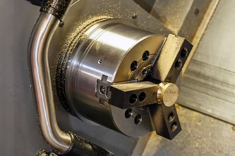
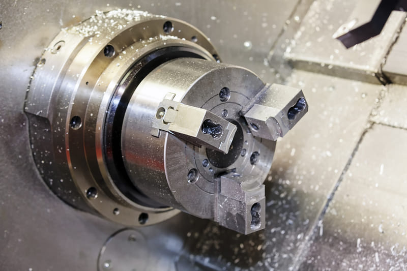
Chuck: How Does It Secure Precision on a CNC Lathe?
If the spindle spins the part, the chuck is what keeps it in place. Without a reliable chuck, even the best CNC lathe loses accuracy.
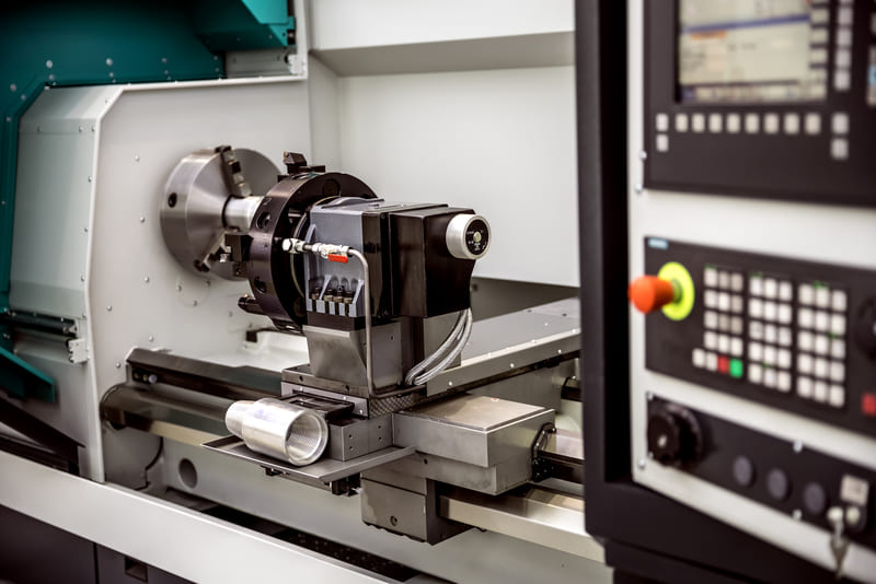
The chuck is the gripping mechanism mounted on the spindle of a CNC lathe. It holds the workpiece firmly in place during rotation, ensuring stability and concentricity throughout the machining cycle.
Why Chucks Matter in CNC Turning
The chuck is the first point of contact between the machine and the material. It needs to clamp with just the right force—enough to resist centrifugal and cutting forces without deforming the part. An incorrect grip leads to eccentric rotation, vibrations, poor surface finish, and dimensional errors.
Types of CNC Lathe Chucks
| Chuck Type | Description | Use Case |
|---|---|---|
| 3-Jaw Chuck | Self-centering, grips round and hex stock quickly | General-purpose work, high throughput |
| 4-Jaw Independent Chuck | Manually adjustable jaws, not self-centering | Irregular shapes, offset turning, square parts |
| Collet Chuck | Provides full 360° clamping with high concentricity | Precision small parts, high-RPM machining |
| Hydraulic/Pneumatic Chuck | Automatically opens/closes using machine control | Lights-out manufacturing, production lines |
Design Tips for Effective Chucking
- Match Jaw Type to Part Geometry: Use soft jaws for custom profiling; hard jaws for durability.
- Use Dowel Pins or Machined Stops: Prevent axial slip during heavy cutting or drilling.
- Consider Clearance: Ensure jaws don’t interfere with tool paths or chip evacuation.
- Balance the Chuck: Especially at high RPM, an unbalanced chuck causes runout and tool wear.
From the Shop Floor: My Own Lessons
In one project, a client machining aluminum connectors reported inconsistent concentricity on their parts. After inspection, we discovered their 3-jaw chuck jaws were unevenly worn. We switched them to a collet chuck with a customized collet diameter. That change alone improved runout from 0.05 mm to 0.005 mm—critical for their press-fit assemblies.
The Chuck’s True Role in Part Accuracy
Think of the chuck as the foundation of the cutting process. Every micron of deviation at the chuck translates to distortion in the final part. Choosing the right chuck type, maintaining it properly, and adapting it to your part geometry are all essential steps toward precision machining and efficient production.production.
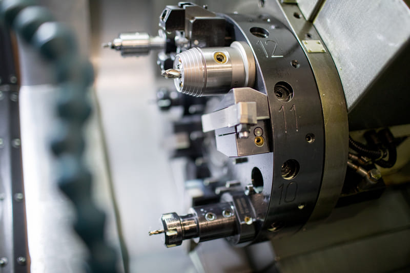
Tool Turret (or Tool Post): What Makes CNC Turning So Efficient?
Ever wondered how a CNC lathe can switch tools in seconds without missing a beat? That’s the tool turret doing its job.
The tool turret—or tool post on simpler machines—is the rotating or static mechanism that holds multiple cutting tools on a CNC lathe. It enables automatic tool changes, minimizes setup time, and supports complex multi-operation cycles without manual intervention.
Why Is the Tool Turret So Critical?
The tool turret is the engine of productivity in a CNC turning center. It allows for a complete machining cycle—from roughing and finishing to threading and boring—without stopping the machine. With programmable indexing, the turret rotates to the correct tool and positions it precisely for the next operation. This reduces idle time and human error while increasing consistency and output.
Tool Turret Types and Configurations
| Turret Type | Description | Best For |
|---|---|---|
| Servo-Driven Turret | Electronically controlled, high-speed indexing | Fully automated, multi-operation jobs |
| Hydraulic Turret | Actuated by hydraulic pressure; robust and reliable | Heavy-duty turning with consistent loads |
| Static Tool Post | Manually adjustable single-tool holder | Prototyping, small batch, or manual lathes |
| Driven Tool Turret | Allows live tooling for milling, drilling, tapping | Complex parts requiring multi-axis operations |
Design Tips for Optimizing the Tool Turret
- Minimize Tool Lengths: Shorter tools reduce deflection and improve surface finish.
- Balance the Turret: Uneven tool loading can cause indexing vibration and wear.
- Use Tool Offsets Properly: Program and calibrate each tool’s geometry in the control panel to ensure accurate switching.
- Label Tools Clearly: Number each position and tool type in both your CAM software and machine control to avoid confusion.
Real-World Impact: From Setup to Lights-Out Production
On a recent project machining a stainless steel manifold with tight ID tolerances, we used a 12-station driven tool turret. This allowed turning, threading, cross-drilling, and finishing—all in one setup. Without the turret, we’d have needed three separate machines and doubled our lead time.
The Heart of Efficiency in CNC Turning
A well-utilized turret makes the CNC lathe a powerhouse of productivity. It automates transitions between operations, supports tool life management, and makes lights-out manufacturing possible. Whether you’re running a basic setup or a fully driven turret with live tooling, this component is where precision meets efficiency.
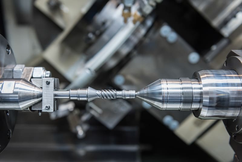
Tailstock: Why It’s Crucial for Long, Slender Workpieces?
Having trouble with part deflection or chatter during long turning operations? You likely need proper tailstock support.
The tailstock is the moveable component on a CNC lathe that supports the opposite end of the workpiece from the headstock. It plays a vital role in stabilizing long or slender parts, especially during high-precision or heavy-cutting cycles.
What Does a CNC Lathe Tailstock Do?
The primary function of the tailstock is to prevent deflection and vibration when machining parts with high length-to-diameter ratios. It uses a center—either live (rotating) or dead (static)—to apply axial pressure to the end of the workpiece. This stabilizing force ensures dimensional accuracy and prolongs tool life.
Tailstock Features and Options
| Feature | Benefit |
|---|---|
| Live Center | Minimizes friction and heat during rotation |
| Programmable Positioning | Automated engagement and retraction increase production speed |
| Quill Lock and Stroke Adjustment | Fine-tunes axial pressure and travel limits |
| Drill Chuck or Tap Adapter | Allows drilling, reaming, and tapping from the tailstock side |
When Should You Use a Tailstock?
- Long Parts: If your workpiece is more than 3–4× longer than its diameter, tailstock support is often necessary.
- Thin Walls: Prevents chatter and wall deformation during light finishing passes.
- Heavy Cuts: Helps stabilize the part under aggressive roughing loads.
- Axial Machining: Essential for operations like deep-hole drilling or tapping that apply end pressure.
Design and Setup Considerations
Ensure your tailstock center aligns precisely with the spindle centerline to avoid off-axis pressure. Use dial indicators during initial setup or rely on machine self-alignment features if available. Also, ensure the pressure exerted by the tailstock does not distort thin-walled components—adjust quill preload accordingly.
Real Example: Supporting High-Aspect-Ratio Parts
We once machined a 500 mm long titanium rod with a 12 mm diameter. Without tailstock support, the part would deflect significantly during turning. With a live center and low-pressure tailstock engagement, we achieved ±0.01 mm concentricity across the entire length without vibration marks or tool wear issues.
Tailstock: The Unsung Hero of Turning Stability
While often overlooked, the tailstock is one of the most essential components in CNC lathes for precision turning of long or flexible parts. Its correct use ensures stability, accuracy, and repeatability—especially in mission-critical industries like aerospace and medical machining.e tailstocks can automatically position based on part length, enabling lights‑out machining.
Bed: Why Is the CNC Lathe Bed the Backbone of Precision?
Experiencing inconsistent dimensions or poor surface finishes? The problem might lie beneath your machine—literally—in the bed structure.
The bed is the foundational base of a CNC lathe. It supports all moving components, aligns key axes, and absorbs machining vibrations. Without a rigid, precisely manufactured bed, even the most advanced tools can’t deliver consistent part quality.
What Is the CNC Lathe Bed?
The bed is a large, heavy, and often monolithic structure made from high-stability materials like cast iron, composite epoxy granite, or polymer concrete. Its primary purpose is to ensure long-term geometric stability and alignment across the machine’s lifespan. The bed serves as the track along which the carriage and tailstock travel and anchors the headstock firmly in place.
Key Bed Characteristics and Components
| Feature | Function |
|---|---|
| Guideways (Ways) | Precision-ground rails for smooth linear movement |
| Mounting Base | Supports headstock, tailstock, and carriage |
| Chip Evacuation Channels | Directs swarf away from moving parts |
| Coolant Reservoir | Houses the fluid used during cutting processes |
Materials Matter: Cast Iron vs. Polymer Concrete
- Cast Iron: Traditional material with excellent vibration damping and thermal stability.
- Polymer Concrete (Epoxy Granite): Offers even better vibration absorption and is used in ultra-high-precision machines.
- Steel Weldments: Common in budget machines; lighter but may deform over time under stress.
Why Bed Precision Is Non-Negotiable
The geometry of the bed dictates the alignment of the tool with the workpiece. Any deviation—no matter how small—can lead to tapered parts, tool chatter, or uneven surface finishes. In high-precision industries like medical machining or aerospace, even microns matter.
Real Example: Diagnosing Misalignment from a Warped Bed
At one point, a customer reported that all turned shafts were consistently tapering by 0.03 mm over 300 mm. After investigating, we found the root cause: a misaligned bed due to improper leveling and shipping stress. Releveling and regrinding the ways restored dimensional accuracy and eliminated the issue entirely.
Maintenance Tips for CNC Beds
- Level the bed using precision leveling jacks during installation
- Check guideway wear every 12–18 months with dial indicators
- Keep chip trays and way covers clean to avoid scoring
- Inspect for coolant leaks that may seep into mounting bolts
Conclusion: The Bed as a Silent Enabler of Accuracy
The CNC lathe bed doesn’t move, cut, or rotate—but without it, none of those things would happen accurately. A well-engineered and maintained bed is essential for consistent performance, geometric precision, and vibration-free machining in any production environment.
Carriage: How Does the Carriage Drive CNC Lathe Precision?
Getting chatter on a finish pass or inconsistent diameters? Your carriage setup could be the silent culprit.
The carriage is the dynamic backbone of the CNC lathe’s tool motion. It carries, positions, and supports the cutting tool as it follows programmed paths along the machine’s X and Z axes. Without a properly functioning carriage, even the best tooling or spindle setup won’t yield accurate, repeatable results.
What Is the Carriage on a CNC Lathe?
The carriage is the sliding mechanism that rides on the precision-ground ways of the lathe bed. It houses several sub-components that work together to deliver controlled tool movement across both linear axes. The entire cutting action of a CNC lathe—from facing to turning to threading—relies on the carriage’s rigidity, precision, and responsiveness.
Main Carriage Components
| Component | Description |
|---|---|
| Saddle | Base of the carriage that rides along the bed’s guideways |
| Cross-slide | Moves perpendicular (X-axis) to the spindle axis |
| Compound Rest | Allows angular tool positioning for threading or taper turning |
| Tool Post (or Turret) | Holds the cutting tool and indexes between tool stations |
Servo Control & Ball Screw Drive
In CNC lathes, the carriage movement is powered by precision-ground ball screws driven by high-torque servo motors. This setup allows micron-level positioning accuracy and smooth interpolated motion—critical for operations like contouring or threading.
Key Benefits of a Well-Designed Carriage
- Stable, chatter-free cutting even under high loads
- Accurate tool positioning across long cuts
- Repeatable results in multi-part production
- Quick tool changes via integrated tool turret
Common Carriage Issues (and Fixes)
- Backlash in Cross-Slide: Check for worn ball nuts or misaligned bearings
- Sticking or Jerky Motion: Often caused by way contamination or dried lubrication
- Excessive Play: Inspect for worn gibs or loose saddle bolts
Personal Experience: Diagnosing a Tapered Cut
Once, a client’s parts were coming out consistently tapered. After ruling out the spindle and tailstock, we traced the issue to worn cross-slide ways. A quick realignment, coupled with way scraping and lubrication restoration, fixed the geometry immediately. It was a clear reminder: never underestimate the carriage’s influence on part shape.
Pro Tips for Carriage Setup
- Check and adjust gib tightness quarterly
- Use synthetic lubricants to reduce wear and thermal distortion
- Set proper servo acceleration to avoid tool chatter at corners
- Ensure the compound rest is locked during automated cycles
Conclusion: The Carriage Is the Machine’s Guiding Hand
From fine-tuning surface finishes to ensuring profile accuracy, the carriage serves as the guiding hand of the CNC lathe. When it operates flawlessly, every other component—from the spindle to the control panel—can reach its full potential in delivering consistent, high-quality results.
Servo motors control these axes precisely for complex, multi-axis turning operations.
Control Panel / CNC Unit: What Does the CNC Brain Really Do?
Ever wonder how a lathe knows when to start, stop, and change tools? It’s all thanks to the control panel—the nerve center of CNC operations.
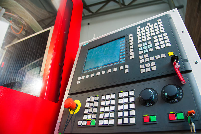
The control panel, often referred to as the CNC unit, is the digital command hub that interprets your G-code instructions and translates them into coordinated machine movements. It manages everything from spindle speed and feed rates to tool selection and alarm detection. In essence, it’s the intelligence that transforms digital design into physical reality.
Core Functions of a CNC Control Panel
- G-code Interpretation: Reads and executes machining programs line-by-line
- Axis Control: Synchronizes X, Z, and turret motion with micron-level precision
- Spindle Regulation: Adjusts RPM in real-time based on program commands
- Tool Management: Coordinates turret indexing and tool offsets
- Diagnostics & Safety: Detects faults, overloads, and enables emergency stops
What’s On the Panel?
| Component | Function |
|---|---|
| Display Screen | Visual interface showing G-code, tool position, and alarms |
| Keypad / Touchscreen | Used to input commands, load programs, and navigate menus |
| Cycle Start / Stop | Begins or halts the active program |
| Override Dials | Manually adjust feed, spindle speed, or rapid traverse percentages |
| Emergency Stop (E-Stop) | Immediately shuts down all motion and power to prevent accidents |
Popular CNC Control Brands
- Fanuc: Industry standard for high-reliability manufacturing
- Haas: Common in U.S. job shops, known for intuitive interface
- Siemens: Strong in European and advanced automation markets
- Mitsubishi: Popular in Asia, known for servo control precision
Why It Matters for Operators and Engineers
Understanding how the control unit works isn’t just for programmers. It empowers machinists to:
- Quickly debug tool path issues
- Optimize cycle times using real-time adjustments
- Monitor tool wear through spindle load trends
- Implement mid-cycle inspection pauses or tool offsets
Example: How I Caught a Programming Bug in Seconds
During a prototype run, I noticed the tool was overshooting on a facing cut. A glance at the CNC panel revealed the tool position was 0.4 mm off in the Z-axis. A quick override and edit in MDI mode prevented a costly crash. The control panel’s real-time feedback saved the part—and the tooling.
Best Practices for Using the CNC Control Panel
- Use simulation mode before starting a new program
- Label tool offsets clearly within the program
- Set spindle load alarms to detect dull tools early
- Back up program data weekly to avoid data loss
Takeaway: The CNC Unit Is the Lathe’s Command Center
Without the control panel, a CNC lathe is just a hunk of iron and motors. By mastering the interface, operators can boost productivity, catch errors early, and ensure every part meets spec on the first run.hi.
Coolant System: How CNC Lathes Stay Cool Under Pressure
Excess heat kills precision. That’s why every CNC lathe needs a well-designed coolant system—it’s your silent partner in protecting parts, tools, and tolerances.
The coolant system in a CNC lathe plays a critical role in thermal regulation, chip evacuation, and surface finish. Whether you’re deep-drilling a steel shaft or performing a high-RPM contour cut, proper coolant delivery can make or break your results.
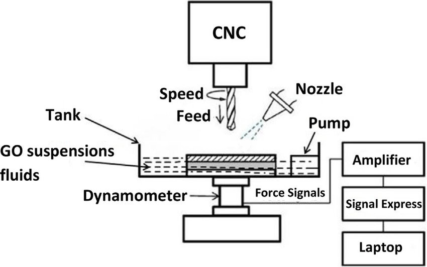
This picture comes from ResearchGate
What Does a Coolant System Do?
- Heat Dissipation: Absorbs and removes heat generated by friction during cutting
- Lubrication: Reduces friction between tool and material, prolonging tool life
- Chip Control: Flushes chips away from the cutting zone, preventing recutting
- Surface Integrity: Helps maintain dimensional stability and smoother surface finishes
Types of Coolant Delivery Systems
| Type | Description | Best Use Case |
|---|---|---|
| Flood Coolant | High-volume fluid directed at tool/workpiece | General turning, threading, boring |
| Mist Coolant | Aerosolized coolant sprayed in small amounts | Light cuts, minimal lubrication setups |
| Through-Tool Coolant (TSC) | Coolant passes directly through the tool body | Deep hole drilling, high-speed precision cutting |
| High-Pressure Coolant | Delivers coolant at 1,000+ PSI | Hard materials, chip-prone operations, aerospace components |
Coolant Fluids: What’s in the Tank?
- Water-Soluble Oils: Most common; mix of oil and water for cooling and lubrication
- Synthetic Coolants: Water-based with chemical additives, no oil content
- Semi-Synthetics: Balance of lubricity and longevity
- Straight Oils: Non-water-based; used for heavy-duty operations
My Go-To Practices for Coolant System Efficiency
- Use tramp oil skimmers to keep the reservoir clean
- Test concentration weekly with a refractometer
- Install magnetic chip separators to reduce clogs
- Flush the system and clean filters monthly for consistent flow
Common Coolant System Issues (and Fixes)
- Low Flow Rate: Check for clogged nozzles or dirty filters
- Foaming Coolant: May indicate incorrect mix ratio—adjust concentration
- Foul Odor: Caused by bacterial growth—clean tank and add biocides
- Coolant Leaks: Inspect hoses, fittings, and seals regularly
Why It Matters
In one instance, I had a high-precision aluminum job that kept showing slight tool marks. After upgrading to a through-tool coolant system and adjusting pressure, the surface finish hit Ra 0.4 μm on the first pass. Coolant wasn’t just a helper—it became the game changer.
Coolant Monitoring Tools You Should Be Using
- Coolant level sensors to prevent dry runs
- Flow meters to confirm delivery pressure
- pH and concentration testing kits for chemical balance
The Bottom Line
The coolant system isn’t just about cooling—it’s integral to precision, safety, and tool performance. Treat it as seriously as your tooling strategy or G-code optimization. Without it, your CNC lathe simply can’t deliver production-grade results.
Final Thoughts
Precision doesn’t happen by accident—it’s engineered into every component of your CNC lathe workflow.
Understanding each core component of a CNC lathe—from the headstock and spindle to the control panel and coolant system—equips you to make smarter decisions at every stage of production. Whether you’re programming a G-code cycle or troubleshooting a toolpath issue, knowing how these systems interact empowers you to diagnose problems faster, reduce cycle times, and deliver consistent part quality.
Here’s the truth I’ve learned from years in the industry: Machines are only as good as the people who understand them. And when you master the lathe from bed to turret, your shop doesn’t just run—it thrives.
What You Gain by Knowing Your Lathe Inside Out
- Better Process Optimization: Choose tools, speeds, and feeds with confidence
- Faster Problem-Solving: Isolate performance issues down to specific components
- Lower Maintenance Costs: Prevent breakdowns with proactive care
- Improved Part Quality: From first-off inspections to mass production
Put Knowledge Into Action
Don’t treat your CNC lathe like a black box. Walk your floor. Talk to your operators. Listen to the hum of your spindle and watch how coolant clears chips. Every component tells a story—and when you read it right, you gain the power to control quality, delivery, and cost in one of the most competitive spaces in modern manufacturing.
Still refining your CNC lathe setup? Our team at Onlyindustries is always here to help.
Let Onlyindustries Help You Deliver Precision
Even the best machines need expert support to reach their full potential.
At Onlyindustries, we don’t just operate CNC lathes—we fine-tune them to your design goals, production schedules, and quality requirements. Whether you’re launching a new prototype or scaling up for a multi-year production contract, our engineers work directly with you to bridge the gap between concept and reality.
What makes us different is simple: We approach every lathe project with a deep understanding of the machine and the part. We know the challenges of holding micron-level tolerances. We understand that long shafts deflect and that tight tolerances in titanium aren’t the same as in aluminum. And we never let a poorly chosen chuck or underpowered spindle compromise your product.
Why Partner with Onlyindustries?
| Capability | Benefit |
|---|---|
| Multi-Axis CNC Lathes | Machining complex geometries in fewer setups |
| DFM Reviews | Reduce machining time and increase manufacturability |
| Certified Quality Control | ISO-compliant processes and CMM inspections |
| Quick Turnaround | Speed up your project without sacrificing quality |
| Flexible Volume Support | From single prototypes to thousands of units |
Industries We Serve
- Aerospace – Fuel system components, bushings, titanium brackets
- Automotive – Shafts, gear blanks, transmission parts
- Medical – Surgical implants, bone screws, device housings
- Industrial – Hydraulic pistons, threaded rods, sensor mounts
We’re not just your vendor—we’re your machining partner. That means transparent communication, honest feedback, and a commitment to getting your parts right the first time, every time.
Let’s turn your precision requirements into reality. Contact Onlyindustries today for a custom quote or technical consultation.