Skip to content
 In the world of CNC machining, G-code is the universal language that tells machines what to do—from rapid positioning to precision cuts. Whether you’re manufacturing aerospace components, complex medical parts, or automotive brackets, mastering G-code can unlock faster, more accurate, and more efficient machining.
This guide provides a comprehensive overview of G-code: what it is, how it works, and why it’s still indispensable—even in the era of advanced CAM software.
What Is G-Code?
CNC machining can’t function without clear communication—and G-code is the language machines speak. Yet, many overlook just how foundational it is to performance and precision.
G-code is the standardized programming language used to instruct CNC machines how to move and operate. It tells the machine *what to do*, *where to go*, *how fast to move*, and *when to act*. Each line in a G-code file represents a specific command that executes part of the machining cycle—turning digital designs into physical components with micron-level accuracy.

Let’s break it down from the ground up so you’re not just using G-code—but leveraging it for better results on the shop floor.
How Is G-Code Structured?
G-code isn’t random letters and numbers—it’s logical, modular, and universally recognized by most CNC machines. Each command line (or “block”) in a G-code program is made up of different elements that control machine motion and behavior.
A typical line might look like this:
G01 X50 Y25 Z-5 F200| Code | Meaning |
|---|---|
| G01 | Linear interpolation (a controlled cutting move) |
| X50 Y25 | Move tool to X = 50 mm, Y = 25 mm |
| Z-5 | Lower tool to Z = -5 mm (cutting depth) |
| F200 | Set feed rate to 200 mm/min |
Block Elements Explained:
- G-codes (G01, G00, etc.): Dictate motion commands
- M-codes (M03, M08, etc.): Control machine functions like spindle and coolant
- X, Y, Z: Position values for axes
- F: Feedrate (speed of tool movement)
- S: Spindle speed (RPM)
- T: Tool number selection
Why It Matters: The Backbone of CNC Automation
Despite the rise of CAM (Computer-Aided Manufacturing) systems that generate G-code automatically, understanding the language behind the curtain is invaluable. As someone who works closely with machinists and engineers, I’ve seen first-hand how even minor manual tweaks to G-code can:
- Prevent tool crashes by correcting positioning errors
- Improve surface finish by adjusting feed/speed
- Reduce cycle times through optimized moves

In one case, we reprogrammed a customer’s part manually and cut machining time by 22%—simply by restructuring the toolpath with more efficient G-code blocks.
When You Should Write or Edit G-Code Manually:
- Debugging unexpected machine behavior
- Running test cuts or prototypes
- Implementing probing routines or custom macros
- When CAM software fails to deliver the needed flexibility
CAM vs G-Code: They’re Not Mutually Exclusive
Think of CAM software as a translator—but if you can speak the native language (G-code), you’ll always have the upper hand. CAM generates G-code, but it doesn’t always optimize for context. Manual G-code writing or refinement remains a powerful tool in your CNC toolkit.
| Function | CAM Software | Manual G-Code |
|---|---|---|
| 3D Toolpath Generation | ✅ | ❌ |
| On-the-Fly Edits | ❌ | ✅ |
| Macro/Probe Integration | ❌ Limited | ✅ Complete Control |
| Error Debugging | ❌ | ✅ |
Conclusion
G-code is the foundation of CNC machining—a language every operator, engineer, and designer should at least understand, even if they never plan to write a full program manually. It’s the key to greater control, more precise adjustments, and a deeper understanding of how designs translate into machined reality.
Why G-Code Still Matters?
Modern CAM tools can generate G-code in seconds, but relying on automation alone creates blind spots. When things go wrong—or when you’re pushing for tighter precision—manual G-code knowledge is irreplaceable.
G-code still matters because it gives you direct, low-level control over your CNC machine. It enables on-the-fly problem solving, customization, and optimization that pre-built CAM strategies can’t always handle. Whether you’re troubleshooting, refining toolpaths, or fine-tuning a process, knowing G-code is a skill that separates good machinists from great ones.
Here’s why, even in a world of advanced software, G-code still earns its place on the shop floor.
G-Code Enables Real-Time Problem Solving
When a part isn’t cutting cleanly or your toolpath collides with a clamp, waiting on a CAM reprogram isn’t always feasible. I’ve personally jumped in and edited just a few lines of G-code to fix a Z-depth error or tweak a radius—cutting hours off a production delay.
Knowing how to identify and modify specific G and M commands means:
- Fewer interruptions in production
- Faster first-article approvals
- Rapid changes for prototyping and R&D
Example:
G01 Z-2.000 F100  ; Incorrect depth causing bottom gouging
→
G01 Z-1.800 F100  ; Quick correction without reprogramming
It Gives You Performance-Level Optimization
CAM-generated toolpaths are safe—but not always fast. For parts that repeat across thousands of cycles, shaving even 5 seconds off a routine can translate into serious savings.
- Shorten retract heights (e.g., changing G00 Z10 to G00 Z5)
- Refine feed rates per material cut zone
- Remove redundant moves or slow transitions
Manual code edits often result in tighter tolerances, better tool life, and smoother finishes.
It Provides Diagnostic Clarity
Machine crashes are costly. But with G-code fluency, you can step through the program line-by-line to isolate what happened—and prevent it from recurring. CAM doesn’t always show the “why” behind tool movement. G-code does.
| Issue | How G-Code Helps |
|---|---|
| Unexpected spindle reversal | Check for misplaced M03/M04/M05 |
| Tool gouging or scrap | Verify Z-depth and feed rate commands |
| Coolant flooding at wrong time | Adjust M08/M09 sequence |
It Unlocks Machine Capabilities CAM Can’t Reach
Some advanced features—like probing routines, custom macro subroutines, and synchronized multi-axis movements—are easier (and sometimes only possible) via manual G-code.
Use Cases That Demand Manual Input:
- In-machine measurement and adaptive offset updates
- Sequential tool-based part probing
- Bar feeding, tailstock actuation, and live tooling coordination
It Supports Learning and Communication
Even if you’re not writing full programs by hand, understanding G-code helps you communicate better with machinists, troubleshooters, and CAM programmers. It gives you insight into what the machine will actually do—not just what the software shows.
Conclusion
G-code still matters because CNC machines still speak it—and they always will. It’s a vital skill that empowers you to correct issues faster, optimize better, and produce with confidence. In a world where automation is everywhere, manual knowledge is your safety net and your secret weapon.s.
Basic G-Code Structure: How Does It Work?
Ever looked at a G-code program and felt lost in a sea of letters and numbers? You’re not alone. But once you understand the structure, G-code becomes surprisingly logical—and incredibly powerful.
At its core, a G-code program is a sequence of instructions that tell your CNC machine exactly what to do. Each line represents one operation: a move, a speed change, a tool shift, or a command to turn the spindle on or off. Knowing how to read and write this structure gives you the power to program manually, troubleshoot issues, and optimize performance at the code level.

Let’s break it down.
What Is a G-Code Block?
Each G-code command line is called a “block.” A block typically includes a combination of letters and numbers that represent machine actions.
A basic block might look like this:
N10 G01 X50 Y25 Z-5 F200
Here’s what each part means:
| Code | Description |
|---|---|
| N10 | Line number (optional but helpful for organization) |
| G01 | Linear feed motion (controlled cutting move) |
| X50 Y25 | Move to X=50, Y=25 coordinates |
| Z-5 | Move tool down to Z = -5 mm (cutting depth) |
| F200 | Feedrate set to 200 mm/min |
Core Elements of a G-Code Block
Every G-code block may include a mix of the following letters:
- G: Preparatory function (e.g., G00 for rapid, G01 for cut)
- M: Miscellaneous function (e.g., M03 for spindle on, M30 for program end)
- X, Y, Z: Axis position targets
- F: Feed rate (in mm/min or inches/min)
- S: Spindle speed (RPM)
- T: Tool number (T01, T02, etc.)
- H: Tool length offset (used with G43)
- D: Tool diameter offset
Example Block With Multiple Elements
N20 G43 H01 T01 S1500 M03
This means:
- Activate tool length offset #1 (H01)
- Use tool #1 (T01)
- Set spindle speed to 1500 RPM (S1500)
- Turn spindle on clockwise (M03)
Block Organization and Program Flow
G-code programs usually follow this general structure:
- Start – Set units, planes, positioning mode
- Spindle and Tool Setup – Select tool, set speed
- Cutting Movements – G01, G02, G03 blocks
- Retract/End – Return to safe height, turn spindle off
Typical Start-Up Sequence:
G21        ; Set units to millimeters
G90        ; Use absolute positioning
G17        ; XY plane selection
G40 G49    ; Cancel cutter compensation and tool length offset
What Are Modal vs. Non-Modal Commands?
Modal commands remain active until changed. For instance, once G01 is set, every subsequent line assumes linear motion unless a new G-code (like G00) is introduced.
G01 X10 Y10 F150  ; Cutting move
X20 Y15           ; Still G01 (linear cut)
Non-modal commands, like G04 (dwell), only affect the line they’re on.
Adding Comments
You can annotate G-code with comments using parentheses:
G01 Z-2.0 F150 (Plunge into material)
This helps during debugging or team collaboration.
Conclusion
Understanding the basic structure of G-code transforms your programming from guesswork to precision control. Every line, every letter, and every feed rate matters—and once you know how to use them, you gain unmatched confidence in how your CNC machine behaves. Master this foundation, and you’ll be prepared for even the most complex programming challenges.
Commonly Used G-Codes: What Are the Core Commands in CNC Programming?
Feeling overwhelmed by the long list of G-codes in CNC machining? Don’t worry—most day-to-day operations rely on a relatively small, manageable set of commands that every CNC programmer should know.
Commonly used G-codes are the backbone of CNC machining. These are the commands that drive movement, control direction, select planes, and manage positioning systems. Understanding these essentials gives you the power to program, optimize, and troubleshoot effectively—even without fancy CAM software.
Let’s decode the ones that matter most.
What Do G-Codes Actually Do?
G-codes (Geometric codes) are instructions that define machine motions and positioning. Most of them fall into one of these categories:
- Linear and circular movements
- Positioning (absolute or incremental)
- Plane selection
- Coordinate system commands
- Tool control and pauses
Below is a table of the most commonly used G-codes and what they control:
| G-Code | Function | Typical Use |
|---|---|---|
| G00 | Rapid Positioning | Fast, non-cutting movement to a target position |
| G01 | Linear Interpolation | Cutting straight lines at controlled speed |
| G02 | Circular Interpolation (Clockwise) | Cutting arcs or circles in the CW direction |
| G03 | Circular Interpolation (Counter-Clockwise) | Cutting arcs or circles in the CCW direction |
| G04 | Dwell | Pause for a set time (e.g., for drilling or dwell time) |
| G17 | Select XY Plane | Defines 2D movement in the XY plane (default) |
| G18 | Select XZ Plane | Used in lathe or mill turning for vertical profiles |
| G19 | Select YZ Plane | Used for side or profile cuts on vertical mills |
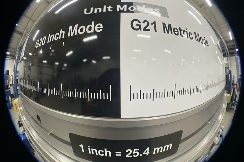
| G20 | Set Units to Inches | Used in US shops; all dimensions in inches |
| G21 | Set Units to Millimeters | Used internationally; dimensions in mm |
| G28 | Return to Machine Home | Resets all axes to their home positions |
| G90 | Absolute Positioning | Positions based on a fixed origin (0,0,0) |
| G91 | Incremental Positioning | Positions relative to the tool’s current location |
How to Use These in Real Programs
Here’s a quick snippet showing how common G-codes interact in practice:
G21 G90 G17        ; Set mm units, absolute mode, and XY plane
G00 X0 Y0          ; Rapid to origin
G01 Z-5 F150       ; Controlled plunge to -5 mm
G02 X20 Y20 R10    ; Cut clockwise arc with 10 mm radius
G00 Z5             ; Rapid retract
Modal vs. Non-Modal G-Codes
Modal G-codes remain active until changed. For instance, G01 stays on until you switch to G00 or another motion command.
Non-modal codes like G04 (dwell) apply only on the line they appear on. Always know what mode you’re in—mixing up modal states can lead to tool crashes or wasted time.
Why Memorizing the Top 10 G-Codes Is Enough to Start
You don’t need to memorize hundreds of commands to begin programming effectively. If you understand and can use the 10–15 most common G-codes, you can write basic to intermediate programs with confidence. As your skills grow, you’ll naturally learn more complex cycles like canned drilling (G81–G89) or macro calls (G65).
Conclusion
Common G-codes are like a CNC machine’s vocabulary—just a handful of them enable you to tell it everything from “move fast” to “cut slow and precise.” Once you grasp how they control movement, direction, and positioning, you’ll be equipped to read and write efficient, error-free programs. These aren’t just lines of code—they’re your key to controlling one of the most powerful tools in modern manufacturing.
M-Codes: Machine Control Commands – What Do They Do in CNC Programming?
G-code handles motion, but it’s the M-codes that make your CNC machine *do things*. From starting the spindle to controlling the coolant, M-codes are the silent workhorses managing the critical support functions that enable safe and productive machining.
M-codes, or miscellaneous function codes, tell the CNC machine when to turn systems on or off, pause operations, or switch tools. If G-codes are the “where” and “how fast,” then M-codes are the “when” and “what next.”
Let’s explore the most common M-codes you’ll use on the shop floor or in a G-code program.
What Are M-Codes in CNC Programming?
M-codes are non-motion commands that manage machine-related operations. They work alongside G-codes but focus on actions like:
- Starting or stopping the spindle
- Turning coolant on/off
- Pausing or ending a program
- Executing tool changes
Each M-code is a short command—typically two or three characters (e.g., M03)—that activates a machine behavior.

Common M-Codes and Their Functions
| M-Code | Function | Typical Use Case |
|---|---|---|
| M00 | Program Stop | Pauses the program—useful for manual inspection or intervention |
| M01 | Optional Stop | Stops program only if operator has “optional stop” switch enabled |
| M02 | End of Program | Terminates the program (older systems) |
| M03 | Spindle ON (Clockwise) | Turns spindle on in the forward direction |
| M04 | Spindle ON (Counterclockwise) | Used for left-hand tools or specific operations |
| M05 | Spindle OFF | Stops spindle rotation |
| M06 | Tool Change | Triggers the automatic tool changer (ATC) to switch tools |
| M08 | Coolant ON | Activates flood or mist coolant during cutting |
| M09 | Coolant OFF | Shuts off all coolant flow |
| M30 | End of Program + Reset | Stops program, resets the machine, and rewinds code to start |
Dive Deeper: How M-Codes Are Used in Practice
Integrating M-Codes into Your Workflow
When I’m writing or reviewing G-code, I use M-codes to precisely control my setup sequence and post-cutting procedures. For example, a typical cycle might look like this:
M06 T01        ; Change to tool 1
M03 S1500      ; Spindle on at 1500 RPM (clockwise)
M08            ; Coolant on
G01 Z-2 F150   ; Feed down to cutting depth
...
M09            ; Coolant off
M05            ; Spindle off
M30            ; End program and reset
This block not only moves the tool and controls feedrates but also ensures proper tool cooling, chip evacuation, and safe shutoff at the end of the operation.
Tips for Reliable M-Code Usage
- Always place M-codes on a separate line for clarity and to reduce parsing issues
- Check your controller’s documentation—M-codes are not fully standardized across machines
- Combine M-codes with G-code safety commands like G40 (cancel cutter comp) before tool changes
- Use M01 for optional stops in prototypes or first-article inspections
Controller-Specific Variants
Be aware that M-code meanings can vary slightly depending on the controller brand (e.g., Fanuc vs. Haas). Some high-end machines support extended M-codes like M97/M98 for subroutine handling or M130 for displaying media.
Conclusion
M-codes may be short and simple, but they control everything from your spindle’s spin to your coolant’s flow. A solid grasp of M-code usage will help you write safer, more efficient programs—and give you greater control over your machine’s behavior. Whether you’re swapping tools, pausing for inspection, or shutting everything down after a perfect cut, M-codes are essential to getting the job done right.
Absolute vs. Incremental Modes – What’s the Difference in G-Code Programming?
One of the most common sources of confusion—and machine crashes—in CNC programming is the mix-up between absolute and incremental positioning. If you’re not careful, your tool might move 50 mm too far and ruin a part (or worse, the spindle). Understanding these two modes is critical for writing safe and effective G-code.
G-code uses G90 for absolute positioning and G91 for incremental positioning. These commands define how coordinate movements are interpreted by the machine: relative to a fixed origin or relative to the current tool location.

Let’s break down the difference, when to use each, and how to avoid major programming mistakes.
What Is Absolute Positioning (G90)?
In absolute mode, all coordinates are measured from a fixed origin point—usually (0,0,0). No matter where the tool is, it will always move to the same physical point based on the absolute coordinate values.
Example:
G90
G01 X50 Y50
This command moves the tool directly to the point (50, 50) based on the origin—even if the tool is already at (40, 40) or (0, 0).
Use absolute positioning when:
- You want precise, repeatable toolpaths
- You’re using CAM-generated code or templates
- You need to move between specific locations on the part
What Is Incremental Positioning (G91)?
In incremental mode, all coordinates are relative to the tool’s current position. So if you’re at X10 and command X10 again, the machine will move to X20.
Example:
G91
G01 X10 Y10
This command moves the tool 10 units further along X and Y from its current position—whether that’s from (0,0), (30,30), or any other point.
Use incremental positioning when:
- You want to repeat the same motion multiple times (e.g., drilling holes in a grid)
- You’re writing custom macros or subroutines
- You want compact code for looped movements
Dive Deeper: Programming Implications and Best Practices
How I Use G90 vs G91 in Real Projects
When I’m working with complex surface features or multi-tool programs, I almost always default to G90 for safety. It’s predictable, especially when switching tools or returning to a known home point. For repetitive patterns—like bolt hole circles—I switch to G91 because it saves time and simplifies the code.
Mixing Modes: Proceed with Caution
You can switch between G90 and G91 within the same program, but you must be intentional:
G90
G01 X20 Y20 ; Move to absolute (20,20)
G91
G01 X10 Y0  ; Move 10 units right from (20,20)
G90
G01 X0 Y0   ; Return to origin
Tip: Always reset back to G90 at the end of the program to avoid confusion in the next cycle.
Real-World Application Table
| Use Case | Best Mode | Why? |
|---|---|---|
| Engraving a logo at multiple locations | Incremental (G91) | Offsets are relative; same motion repeats |
| Facing or contouring a part | Absolute (G90) | Tool must follow exact global coordinates |
| Drilling a series of holes in a pattern | Incremental (G91) | Repeats same move with short code |
| Multi-operation machining (rough to finish) | Absolute (G90) | Coordinate tracking and tool changes are easier |
Conclusion
G90 and G91 are foundational to CNC programming. One refers to a map, the other to a step. Used correctly, they help you machine with accuracy, efficiency, and safety. Just remember: switching between modes requires awareness—and the right mindset to avoid costly mistakes.
Toolpath Control Using G-Code – How Do You Command Precise Machine Movements?
Even the most advanced CNC machine is useless without the right instructions. At the heart of those instructions lies G-code—the language that defines the toolpath. Whether you’re cutting a straight edge, a smooth arc, or a deep pocket, G-code tells the machine exactly what to do and how to move.
Toolpath control is about more than just “moving from A to B.” It’s about accuracy, speed, efficiency, and protecting your tools and materials. With the right G-code commands, you can dictate how tools cut, how deep they go, what direction the spindle spins, and how fast the entire operation proceeds.

Let’s explore how G-code puts you in complete control of your machining process—and how to make the most of it.
What Is Toolpath Control Using G-Code?
Toolpath control refers to programming the exact movements and behaviors of the cutting tool using G-code instructions. These include position coordinates, motion commands, feedrates, speeds, coolant activation, and tool changes.
Key Elements of Toolpath Control:
- Motion Type: Linear (G01), rapid (G00), circular (G02/G03)
- Positioning: Absolute (G90) or incremental (G91)
- Feedrates: Set with F-word (e.g., F100)
- Spindle Control: M-codes like M03 (CW), M05 (stop)
- Depth and Z-axis Control: Z- values for plunges or retraction
- Coolant and Dwell: M08 (coolant ON), G04 (pause)
Dive Deeper: How I Use G-Code for Complete Toolpath Mastery
1. Defining Motion and Geometry
To create any feature—pocket, slot, contour—I use G00 for positioning and G01 for linear cutting. For curves, G02 and G03 control clockwise or counterclockwise arcs.
G00 X0 Y0         ; Rapid move to start point
G01 Z-2 F150      ; Feed down to cutting depth
G01 X50 Y0 F100   ; Linear cut to the right
G03 X70 Y20 R20   ; CCW arc to new point with 20mm radius
This basic pattern ensures precision, efficient transitions, and a smooth finish on complex geometries.
2. Managing Spindle and Coolant for Process Stability
Toolpath reliability isn’t just about position—it’s about stable cutting. I always set spindle direction and RPM (S-word) before the cut:
M03 S1200         ; Spindle ON, clockwise, 1200 RPM
M08               ; Coolant ON
At the end of the operation, I shut them down cleanly:
M09               ; Coolant OFF
M05               ; Spindle OFF
3. Feedrate and Depth Control
Different materials and tools require different speeds. I adjust feedrates with the F-word and ensure depth control on the Z-axis for every operation:
G01 Z-0.5 F60 ; Light cut for fine finish
In tight-tolerance jobs, I use multiple light passes rather than one deep cut—better surface integrity and tool life.
4. Tool Selection and Safe Retracts
Tool changes and height settings are a big part of multi-op jobs. For safety and precision, I use:
T02 M06           ; Select tool 2
G43 Z5 H02        ; Apply tool offset H02, retract to Z5
This keeps the tool above the part while accounting for offset differences in length or holder setup.
Toolpath Control – Practical Summary Table
| Function | G/M-Code | Description |
|---|---|---|
| Rapid Move | G00 | Quick positioning with no cutting |
| Linear Cut | G01 | Straight-line material removal |
| Arc Cut | G02 / G03 | Clockwise / counter-clockwise curves |
| Spindle Control | M03 / M05 | Turn spindle ON or OFF |
| Coolant | M08 / M09 | Activate or deactivate coolant flow |
| Feedrate | F-word | Control cutting speed (mm/min or in/min) |
| Tool Change | M06 | Switch active tool |
| Tool Height Offset | G43 Hxx | Apply offset from tool table |
Conclusion
Controlling toolpaths through G-code gives you the power to machine smarter—not just harder. Every motion, speed, and tool change becomes a calculated decision that impacts part quality, tool life, and cycle time. When you understand toolpath programming, you move from operator to process engineer—and that’s where the real value lies.
G-Code vs. CAM Software – Which Should You Rely On for CNC Programming?
In CNC machining, both G-code and CAM software are essential tools for creating precise parts. While CAM automates toolpath generation, G-code offers direct control over every movement. Knowing the differences—and when to use each—can dramatically improve your productivity, accuracy, and flexibility on the shop floor.
For many manufacturers, it’s not about choosing one over the other, but understanding how to combine their strengths. Let’s break down what each approach offers, their limitations, and how I use them effectively in real projects.
What’s the Difference Between G-Code and CAM Software?
G-Code is the machine’s native language—a set of instructions that control movements, speeds, feeds, spindle actions, and coolant flow. It’s precise, lightweight, and universal across CNC platforms (with slight variations by controller).
CAM (Computer-Aided Manufacturing) software creates toolpaths from 3D CAD models, then outputs those toolpaths as G-code for the CNC machine. It’s visual, intuitive, and speeds up complex geometry programming.

Dive Deeper: How I Compare G-Code and CAM in Practice
1. Control vs. Automation
When I program directly in G-code, I can control every motion down to the micron—perfect for fine-tuning feeds, speeds, and entry/exit moves. CAM software automates toolpath creation, which is ideal for 3D contours or high-speed machining strategies that would take hours to code manually.
2. Learning Curve
G-code has a steeper learning curve but gives you the ability to debug and modify on the fly. CAM is easier for beginners since it generates code from a graphical interface, but you need to understand G-code to troubleshoot and optimize its output.
3. Flexibility in Production
On urgent jobs, I’ve often edited G-code directly at the machine to adjust feeds for a harder-than-expected material or to change a cutting depth without regenerating the CAM file. CAM shines in pre-production, where simulation and collision detection save costly mistakes.
4. Efficiency with Different Job Types
For repetitive, simple parts—like drilling patterns or basic pockets—I prefer hand-coding G-code for speed and lean files. For complex aerospace brackets or mold cavities, CAM drastically cuts programming time while providing optimized toolpaths for multi-axis machines.
Comparison Table: G-Code vs. CAM Software
| Feature | G-Code | CAM Software |
|---|---|---|
| Programming Speed (Complex Parts) | Slow – manual entry required | Fast – automated toolpath generation |
| Precision Control | High – every command is user-defined | Moderate – depends on software algorithms |
| Ease of Use | Steep learning curve | Beginner-friendly |
| Simulation & Visualization | Manual or third-party tools needed | Built-in 3D simulation |
| On-the-Fly Editing | Yes – direct at the machine | No – requires re-export and reload |
| Best For | Simple, repetitive, or highly customized jobs | Complex, multi-axis, or high-volume runs |
Conclusion
G-code offers ultimate precision and adaptability, while CAM software accelerates complex programming and reduces setup time. In my workflow, I use CAM for initial toolpath creation and G-code for final optimization. Mastering both gives you the best of both worlds—fast programming without sacrificing control.
Advanced Tips for G-Code Programming – Boost Accuracy, Speed, and Reliability
Once you’ve mastered the basics of G-code, the next step is to refine your programming for efficiency, precision, and repeatability. In my experience, applying a few advanced techniques can drastically reduce cycle times, extend tool life, and minimize costly mistakes.
Below, I’ll share the best practices I use when programming G-code for high-performance CNC machining—whether for aerospace titanium parts, precision medical implants, or large production runs.
Why Advanced G-Code Programming Matters
Even with powerful CAM software, the final control over how a machine cuts comes down to the G-code. By integrating optimization techniques directly into your code, you ensure the program runs exactly as intended under real-world shop conditions.
Dive Deeper: My Proven Advanced G-Code Practices
1. Use Comments for Clarity
I make sure to annotate every critical step in my G-code programs using parentheses. This is invaluable for troubleshooting, training new operators, or revisiting a program months later.
(Roughing pass – face cut)
G01 X50 Y25 Z-5 F200
Clear comments reduce confusion, prevent operator errors, and help when multiple programmers work on the same job.
2. Leverage Subroutines (M98/M99)
For repeated features like hole patterns or identical pocketing on multiple faces, I use subroutines to keep my code compact and easy to modify. This avoids duplicating large code blocks and ensures consistency.
M98 P1001 L4  (Run subroutine 1001 four times)
...
O1001
G81 X10 Y10 Z-5 R2 F100
M99
3. Maintain Unit and Mode Consistency
I always set units (G20/G21) and positioning modes (G90/G91) at the start of the program. This prevents unexpected behavior if the machine retains settings from a previous job.
4. Use Modal Commands Wisely
Modal commands stay active until changed. I minimize redundant commands to keep files short and reduce processing time, but I always restate critical modes after tool changes to avoid mishaps.
5. Simulate Before Running
Before I ever hit the cycle start button, I run my program through CAM or machine simulation software. This catches potential collisions, rapid moves into stock, or incorrect retract heights.
6. Optimize Feed and Speed Changes
By strategically adjusting feedrates (F) and spindle speeds (S) mid-cut, I can adapt to varying material conditions—like slowing down when entering a heavy cut, then ramping up for lighter sections.
7. Manage Tool Engagement
For tool longevity, I program lead-in and lead-out moves, arc entries (G02/G03), and ramping where possible. This reduces sudden tool loading and extends cutter life.
Advanced Tips Table
| Tip | Benefit | Example G-Code |
|---|---|---|
| Comments | Improved readability & debugging | (Finish pass – 0.2 mm stock left) |
| Subroutines | Code efficiency & repeatability | M98 P1002 L6 |
| Unit Consistency | Prevents mode errors | G21 G90 |
| Modal Command Control | Avoids unexpected machine behavior | Restating G17/G90 after tool change |
| Simulation | Detects collisions before machining | – |
| Adaptive Feeds/Speeds | Better cut quality & tool life | F250 (rough) → F400 (finish) |
Conclusion
Advanced G-code programming is about more than knowing the commands—it’s about applying them strategically to improve quality, efficiency, and reliability. By using comments, subroutines, mode control, and simulation, I’ve consistently delivered precision parts while avoiding costly downtime. If you want to unlock your CNC machine’s full potential, these techniques are non-negotiable.
Sample G-Code Program: Face Milling Operation – Step-by-Step Breakdown
Understanding a real-world G-code example is one of the best ways to connect theory to actual CNC machining. Below, I’ll walk you through a face milling operation program I’ve used countless times in production—explaining exactly what each line does and why it matters.
Why a Face Milling Example?
Face milling is one of the most common CNC operations for producing flat, accurate surfaces. It’s a perfect example for learning how G-code commands control tool movement, spindle speed, feedrate, and safety sequences.

Dive Deeper: Complete G-Code Example and Explanation
%
O1001 (Face Milling Operation)
G21 G90 G40 G80 G17
G00 X0 Y0
G43 Z5 H01
M03 S1200
G01 Z-2 F200
G01 X50 Y0 F100
G00 Z5
M05
M30
%
Line-by-Line Breakdown
| Line | Code | Explanation |
|---|---|---|
| 1 | % | Start of the CNC program file. |
| 2 | O1001 | Program number for reference on the CNC controller. |
| 3 | (Face Milling Operation) | Comment describing the program’s purpose. |
| 4 | G21 | Set units to millimeters. |
| 5 | G90 | Enable absolute positioning mode. |
| 6 | G40 | Cancel any active cutter radius compensation. |
| 7 | G80 | Cancel any active canned drilling cycles. |
| 8 | G17 | Select the XY plane for machining. |
| 9 | G00 X0 Y0 | Rapid move to the start position in XY. |
| 10 | G43 Z5 H01 | Apply tool length offset H01 and move to 5 mm above part surface. |
| 11 | M03 S1200 | Start spindle clockwise at 1200 RPM. |
| 12 | G01 Z-2 F200 | Feed down to cutting depth of 2 mm at 200 mm/min. |
| 13 | G01 X50 Y0 F100 | Feed across the surface to X50 at 100 mm/min. |
| 14 | G00 Z5 | Rapid retract to 5 mm above the part. |
| 15 | M05 | Stop the spindle. |
| 16 | M30 | End program and reset to the start. |
| 17 | % | End of program file. |
Key Safety and Efficiency Points
- Safety Lines (G40 G80 G17) – Always included to reset the machine to a known safe state.
- Tool Length Offset (G43 H01) – Prevents cutting too deep or crashing into the part.
- Feed Control – Different feedrates for plunging vs. cutting passes optimize time and finish.
Conclusion
Breaking down this face milling example shows how each G-code line contributes to a safe, efficient, and precise operation. By understanding the reasoning behind each command, you can adapt and optimize similar programs for your own parts—whether in prototype work or high-volume production.
Final Thoughts – Why G-Code Mastery Still Matters in Modern CNC Machining
Even in an era where CAM software dominates programming workflows, I’ve learned first-hand that having a solid grasp of G-code is the difference between just running a CNC machine and truly controlling it. Whether I’m troubleshooting a toolpath at 2 a.m. during a rush job or tweaking feedrates to shave seconds off a cycle time, my ability to read, write, and modify G-code directly impacts productivity, part quality, and machine longevity.
If you only rely on CAM-generated code, you’re limited by what the software decides. When you understand G-code, you’re free to:
- Quickly fix errors without restarting a full CAM process
- Optimize programs for different materials, tools, or machine capabilities
- Prevent crashes by spotting dangerous commands before they run
- Experiment with cutting strategies to improve finish and reduce wear
Dive Deeper: The Long-Term Payoff of G-Code Fluency
Over the years, I’ve noticed a recurring pattern: machinists and engineers who can interpret and modify G-code advance faster, troubleshoot better, and deliver more consistent results. This skill doesn’t just save time—it builds confidence in the shop and trust with customers.
Why It’s a Competitive Advantage
| Benefit | Impact on Operations |
|---|---|
| Rapid Problem Solving | Eliminates downtime caused by waiting for CAM edits |
| Process Optimization | Improves cycle times, tool life, and finish quality |
| Cost Control | Reduces scrap and rework through precise adjustments |
| Flexibility | Allows last-minute design changes without a full reprogram |
My Takeaway
Mastering G-code is like learning a trade language. Once you’re fluent, you can walk into any CNC-equipped shop and instantly understand what the machine is doing—and why. It’s the foundation for better decision-making, smoother operations, and higher-quality parts.
Conclusion
G-code remains the bridge between CAD designs and finished parts. By investing the time to understand it, you equip yourself with the skills to optimize performance, ensure safety, and deliver consistent, precision results—no matter the complexity of the project or the capabilities of your CNC machine.
Partner with Experts in CNC Programming
In my experience, even the most advanced machines and premium tooling won’t deliver their full potential without expertly crafted G-code. That’s why partnering with a CNC programming team that understands both the art and science of machining is such a game-changer. At Onlyindustries, we treat every project as a precision challenge, not just a production order.
Our approach blends deep programming expertise with real-world machining experience to ensure that every line of code serves a purpose—maximizing efficiency, improving accuracy, and protecting your investment in equipment and materials.
- Custom G-code Optimization: We refine CAM-generated toolpaths for smoother transitions, reduced cycle times, and minimal tool wear.
- Process Simulation: Every program is tested in simulation to identify and eliminate potential collisions or inefficiencies before they reach the machine.
- Industry-Specific Solutions: From aerospace hard metals to high-polish medical components, we adapt programming strategies to your material and tolerance requirements.
- On-the-Fly Adjustments: When production realities change, our programmers can quickly adjust feeds, speeds, and sequences without halting your schedule.
Dive Deeper: Why Expert Programming Pays Off
Over the years, I’ve seen companies save thousands—sometimes tens of thousands—simply by partnering with skilled CNC programmers. It’s not just about faster cycle times; it’s about reducing scrap, preventing crashes, and extending tool life. Every improvement in code quality has a direct impact on profitability and delivery timelines.
Benefits of Working with Onlyindustries
| Advantage | How It Impacts You |
|---|---|
| Precision G-code Tuning | Achieves better finishes and tighter tolerances |
| Shorter Setup Times | Minimizes downtime and accelerates job changeovers |
| Reduced Tool Costs | Optimized toolpaths extend the life of expensive cutters |
| Improved Throughput | More parts out the door without compromising quality |
Our Commitment
We don’t just deliver code; we deliver confidence. From prototype runs to full-scale production, our team ensures your CNC machines perform at their best. Every job gets the same attention to detail, whether it’s a one-off aerospace component or a high-volume automotive order.
Conclusion
If you want CNC programs that not only run but excel—producing precise, consistent, and efficient results—partnering with Onlyindustries is your best move. Let’s turn your CAD models into flawless, production-ready reality.