Skip to content
 In the world of modern CNC machining, face milling stands out as one of the most essential and versatile operations. From roughing down cast surfaces to preparing critical datum faces, this method plays a vital role in achieving surface flatness, dimensional accuracy, and machining efficiency.
Whether you’re working with aluminum, hardened steels, or composites, understanding face milling will help you improve productivity and part quality. This guide covers everything you need to know — tools, techniques, materials, parameters, and best practices.
What Is Face Milling?
Uneven surfaces can ruin part alignment and reduce dimensional accuracy—face milling is how I correct them quickly and cleanly.
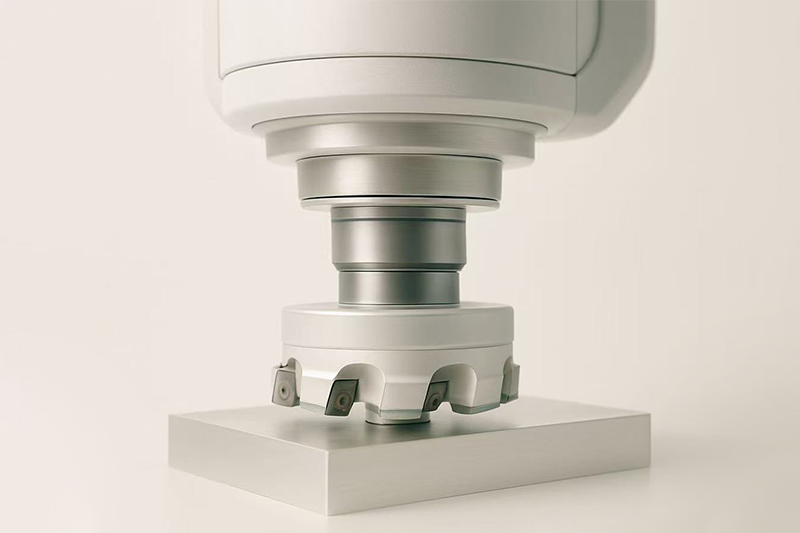
Face milling is a CNC machining process where the flat surface of a rotating tool comes into contact with the workpiece’s top face to create a smooth, even plane. Unlike end milling, which cuts on the sides, face milling engages both the tool’s bottom face and outer edge to efficiently remove material across wide, flat surfaces.
Mastering face milling has saved me hours of rework. It’s the foundational process I use when preparing parts for precision operations—especially when creating datum planes or removing casting scale. Here’s what I’ve learned that makes it work best.
How Does Face Milling Work?
When I run a face milling operation, I rely on a large-diameter cutter equipped with multiple replaceable inserts. The machine brings this cutter down onto the flat surface of the material—usually metal or plastic—and begins its pass across the workpiece. Both the cutting edges on the periphery and the insert bottoms engage the material, producing consistent and high-quality finishes in just one or two sweeps.
Face Milling vs. End Milling
| Feature | Face Milling | End Milling |
|---|---|---|
| Cutting Surface | Bottom and side of tool | Primarily tool side |
| Main Use | Flattening wide surfaces | Profiling, pockets, slots |
| Tool Diameter | Usually larger | Typically smaller |
| Surface Finish | Excellent flatness | Good on detailed features |
Typical Applications
- Preparing stock for secondary machining
- Machining reference planes or datums
- Removing surface scale from castings or forgings
- Creating flat interfaces for part mating
What Makes Face Milling So Effective?
Face milling excels because it combines fast material removal with high surface quality. I’ve used it to flatten large aluminum plates as well as hard steel blocks. With the right tool path and insert grade, it’s incredibly efficient—saving both time and tooling cost. Its versatility across metals and plastics makes it one of the first operations I set up when starting a new CNC project.
The key is balancing tool diameter, insert geometry, and machine stability. When done right, the results speak for themselves: consistent flatness, minimal chatter, and a finish that’s ready for inspection or further machining.
Key Components of a Face Milling Setup
Even the best programming won’t save a poor setup—face milling success starts with having the right components in place.
A face milling setup includes several critical components: the cutter, inserts, arbor or toolholder, and fixturing. Each plays a distinct role in achieving smooth, flat surfaces and tight tolerances. Understanding how they work together has helped me eliminate chatter, extend tool life, and boost surface finish consistency.
If you’re struggling with inconsistent results, there’s a good chance your setup—not your toolpath—is to blame. Here’s a breakdown of the face milling essentials I always verify before hitting cycle start.
1. Face Mill Cutter
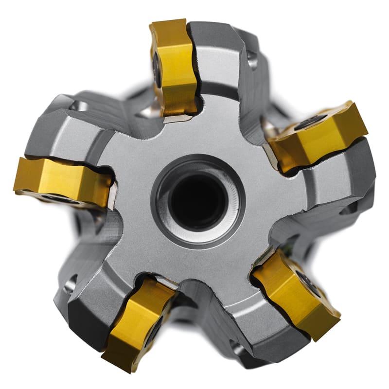
The cutter is the star of the operation. I usually work with shell mills or face mills ranging from 50 mm to 160 mm in diameter, depending on the workpiece size. These tools are built to house multiple carbide inserts and handle both roughing and finishing operations.
Shell Mills vs Fly Cutters
| Type | Advantages | Best Use |
|---|---|---|
| Shell Mill | Multiple inserts, high material removal rate | General-purpose face milling, larger surfaces |
| Fly Cutter | Single insert, fine surface finish | Finishing passes, soft materials |
2. Insert Geometry
The right insert changes everything. Positive rake inserts cut more easily and are my go-to for aluminum. For harder steels and cast iron, I prefer negative rake inserts—they’re tougher and last longer under stress. Coatings like TiAlN or TiCN significantly extend tool life, especially at higher cutting speeds.
Insert Geometry Cheat Sheet
- Positive Rake: Smooth cutting in soft materials, low cutting forces
- Negative Rake: Strong edge, suitable for tough materials
- Coatings: Enhance wear resistance, reduce heat buildup
3. Tool Holder or Arbor
I never overlook this. A solid arbor connection ensures minimal runout and vibration, which directly impacts surface finish. For larger tools, I use a bolt-on shell mill arbor; for smaller setups, ER collets or hydraulic chucks offer more precision. The key is to ensure concentricity and rigidity.
Tips for Tool Holding
- Keep tool overhang to a minimum
- Balance assemblies to reduce vibration
- Use torque specs for insert screws to avoid slippage
4. Workholding & Fixturing
This is the hidden hero. Without a stable, vibration-free workholding solution, even the best face milling setup will fail. I use precision vises, modular fixtures, or vacuum chucks depending on part geometry. For long parts, additional clamping and support blocks prevent chatter and deflection.
Fixture Checklist Before Milling
- Is the part fully supported?
- Is the clamp pressure even and secure?
- Will vibration be an issue at entry/exit points?
Final Thought
Each component in your face milling setup plays a role in part quality, cycle time, and tool wear. Fine-tuning these variables has helped me solve 90% of the surface finish problems I’ve encountered. The next time you face mill, don’t just press start—inspect your cutter, insert geometry, holder, and fixturing. That’s where true consistency begins.
Types of Face Milling Operations
Not every face milling pass is created equal—different surfaces and part geometries call for specific techniques.
Face milling isn’t a one-size-fits-all operation. Depending on your part size, surface requirements, and machine setup, you’ll need to choose the right milling technique to balance speed, quality, and tool life. Over the years, I’ve used each of these strategies to solve very specific production problems—and knowing when to apply which method is a real game-changer.
If you’re only using standard face milling passes, you might be missing out on faster cycle times or better finishes. Here’s how the different methods compare and when I’ve found each one most effective.
Conventional Face Milling
Conventional face milling is the bread and butter of surface machining. The cutter is centered over the workpiece and makes overlapping passes until the entire face is flat.
This is my go-to for general-purpose milling—especially when the surface area fits within the tool’s diameter or just requires a few swipes. It’s also the most beginner-friendly method because it offers good control and uniform chip loads.
Use Cases:
- Machining aluminum plates to a reference plane
- Roughing surfaces before drilling
- Removing forging or casting scale
Partial Face Milling
In partial face milling, the tool covers only part of the surface in each pass. I use this for larger parts that don’t fit under the full diameter of the cutter or when the machine’s travel limits how much I can cover in a single stroke.
It requires extra planning to ensure even step-over and good blending between passes. But when done right, you can face large parts without oversized cutters or setups.
Use Cases:
- Leveling steel plates too wide for the tool
- Facing long extrusion profiles
- Using smaller mills on big parts due to machine constraints
End Milling (Facing)
When you’re dealing with smaller surfaces or narrow pockets, a traditional face mill is overkill. That’s when I switch to end milling using flat-bottomed end mills to “face” the surface.

This isn’t technically “face milling,” but it achieves a similar effect on a smaller scale. It’s ideal for internal cavities, bosses, or when surface area is too tight for a large face mill.
Use Cases:
- Creating reference faces on small brackets
- Flat surfaces inside molds or housings
- Secondary operations after roughing
Fly Cutting
Fly cutting is my choice for ultra-fine surface finishes, especially on soft materials like aluminum. It uses a single cutting insert or tool mounted on a simple fly cutter. While it’s slower than multi-insert tools, it creates mirror-like finishes when dialed in correctly.
Keep feeds slow, depths light, and tool balance perfect. It’s not for heavy-duty material removal but shines on cosmetic surfaces.
Use Cases:
- Finishing aluminum plates for display enclosures
- Precision fixture faces
- Low-speed manual milling setups
Helical Face Milling
Helical face milling involves spiraling down into a surface with a circular ramp motion. I use it on contoured faces or angled surfaces where standard flat passes won’t cut it—literally.
This is more advanced and often used in 5-axis environments or complex mold work. It’s especially useful for achieving consistent engagement and chip load across sloped surfaces.
Use Cases:
- Sloped or angled aluminum components
- Multi-surface die casting molds
- Complex aerospace skins or paneling
Quick Comparison Table
| Operation Type | Tool Type | Best For |
|---|---|---|
| Conventional Face Milling | Shell mill | General flat surfaces |
| Partial Face Milling | Shell mill | Oversized workpieces |
| End Milling (Facing) | Flat end mill | Small pockets and edges |
| Fly Cutting | Single-insert cutter | High cosmetic finishes |
| Helical Face Milling | Multi-axis tool | Angled or 3D surfaces |
Final Thought
Each face milling method has its strengths. By understanding your part geometry, surface requirements, and machine capabilities, you can choose the most efficient and reliable strategy. I’ve learned that optimizing the milling technique—rather than just pushing harder—saves more time and money in the long run.
Materials Commonly Face Milled
Every material machines differently—and face milling demands the right strategy for each.
Face milling is a versatile operation, but that doesn’t mean it’s universal. From my experience, the success of any milling job hinges on understanding how the material behaves under cutting forces. Whether you’re working on aerospace-grade titanium or cost-effective mild steel, tweaking parameters and tool choices for each material type is the key to high-quality results.
Let’s break down the most common materials used in face milling and how to get the most out of each one—because the wrong combination of insert grade or feed rate can quickly turn into chatter, poor finishes, or broken tools.
Face Milling Metals
1. Aluminum
Aluminum is one of the easiest metals to face mill. It allows for high spindle speeds, aggressive feeds, and large depths of cut. Use tools with sharp, positive-rake inserts and polished coatings (or even uncoated) to prevent built-up edge (BUE).
- Recommended Inserts: Polished carbide, sharp geometry
- Coatings: DLC, TiB2
- Coolant: Optional — dry cutting works well
2. Mild Steel & Carbon Steel
This group includes 1018, 1045, and similar grades. These materials are relatively easy to cut but harder than aluminum. Use general-purpose carbide inserts with moderate cutting speeds and a balance of toughness and wear resistance.
- Recommended Inserts: Tough grades with neutral to positive rake
- Coatings: TiAlN, TiCN
- Coolant: Recommended to manage heat
3. Stainless Steel (304, 316)
Stainless steel is notorious for work hardening and causing tool wear. Keep feeds high to avoid rubbing and use coated carbide inserts designed for tough materials. Ensure excellent rigidity in the setup to avoid chatter.
- Recommended Inserts: High-toughness inserts, reinforced cutting edges
- Coatings: TiAlN or AlTiN
- Coolant: Yes — essential for temperature control
4. Cast Iron
Cast iron is abrasive but predictable. Dry machining works well, and negative-rake inserts are often used for better tool life. Avoid coolant unless necessary for surface finish, as thermal shock can cause cracking.
- Recommended Inserts: Tough carbide, negative rake
- Coatings: TiCN, AlCrN
- Coolant: Dry preferred
5. Titanium & High-Temp Alloys
Titanium requires slow cutting speeds, high feed rates, and rigid setups. Insert wear is a real issue due to high temperatures at the cutting zone. Use inserts rated for extreme heat and consider using coolant-through tools.
- Recommended Inserts: Heat-resistant carbide, sharp geometry
- Coatings: AlTiN or nano-layered coatings
- Coolant: Required — high-pressure recommended
Face Milling Plastics & Composites
1. Engineering Plastics (Nylon, Delrin, ABS, PC)
These materials are soft, thermally sensitive, and prone to melting if machined too aggressively. Use sharp tools and high chip loads to evacuate chips quickly and avoid overheating.
- Recommended Inserts: Sharp, polished inserts (sometimes high-speed steel)
- Coolant: Air blast preferred over liquid
2. High-Performance Plastics (PEEK, PTFE)
These are more stable under heat but still require light finishing passes to avoid dimensional inaccuracies. Toolpath strategies must account for thermal expansion and shrinkage.
- Recommended Inserts: Carbide, uncoated or polished
- Coolant: Light air cooling or mist spray
3. Composites (CFRP, GFRP)
Composites are abrasive and delaminate easily. Specialized cutters with diamond coatings (PCD) and negative rake angles are ideal. Speeds must be kept moderate, and feed should be consistent to avoid fiber pullout.
- Recommended Inserts: PCD-tipped or diamond-coated carbide
- Coolant: Dry machining preferred
Face Milling Material Quick Reference
| Material | Tool Coating | Rake Angle | Coolant Use |
|---|---|---|---|
| Aluminum | DLC / TiB2 | Positive | Optional (Dry works) |
| Steel | TiAlN / TiCN | Neutral | Recommended |
| Stainless Steel | AlTiN / TiAlN | Neutral | Required |
| Cast Iron | TiCN | Negative | Dry Preferred |
| Titanium | AlTiN | Positive | Required |
| Plastics | Polished / None | Positive | Air or Mist |
| Composites | PCD / Diamond | Negative | Dry |
Final Thought
Material choice is the foundation of face milling success. The cutter, insert, and parameter setup must be tailored to the unique challenges each material presents. It’s not about having one strategy that works—it’s about having the right one for the job at hand. Trust me, adjusting just a coating or rake angle can be the difference between 20 minutes of downtime and a perfect part the first time.ys match tool geometry and cutting parameters to the material.
Key Face Milling Parameters
Face milling success relies heavily on dialing in the right machining parameters.
When I’m programming a face milling operation, I always pay close attention to the interplay of speed, feed, depth, and tool geometry. Getting these parameters wrong leads to poor finishes, excessive wear, or worse—damaged parts. If you want consistency and performance, you need to master these inputs.
In this section, I’ll walk you through the essential parameters that drive productivity and surface finish quality in face milling operations—and how I personally tune them based on material and tool setup.
Understanding the Core Parameters
| Parameter | Symbol | Definition | Best Practice |
|---|---|---|---|
| Cutting Speed | Vc (m/min) | Linear speed at the tool’s cutting edge | Match to material—aluminum: 300-1000 m/min; steel: 80-180 m/min |
| Feed per Tooth | fz (mm/tooth) | How much the tool advances per insert per revolution | Aluminum: 0.1–0.4 mm; Steel: 0.05–0.2 mm |
| Depth of Cut | ap (mm) | Axial depth the tool removes per pass | Roughing: 2–6 mm; Finishing: 0.2–0.6 mm |
| Width of Cut | ae (mm) | Radial engagement—width of tool in contact | Avoid full-width cutting to reduce chatter |
| Spindle Speed | n (RPM) | Rotational speed of the cutter | Calculated: n = (1000 × Vc) / (π × D) |
| Coolant Use | — | Application of cutting fluid for heat control and chip evacuation | Use with steel/stainless; dry machining OK for aluminum |
Dive Deeper: How I Tune Each Parameter
1. Cutting Speed (Vc)
Cutting speed is critical—too fast, and you risk heat buildup and insert wear. Too slow, and you sacrifice cycle time. I adjust speed based on both the insert coating and the workpiece material. For example, I’ll run 7075 aluminum at 800 m/min with DLC-coated inserts but slow down to 100 m/min for 4140 steel using TiAlN-coated cutters.
2. Feed per Tooth (fz)
This parameter dictates chip thickness. I tend to start with the insert manufacturer’s guidelines and tweak based on surface finish. For finishing, I reduce fz to get a finer chip, improving texture. I always check that chip thinning doesn’t cause rubbing—which leads to work hardening in materials like stainless steel.
3. Depth of Cut (ap)
Depth of cut determines how aggressive you can be. I use a deeper ap during roughing to remove stock quickly, but during finishing, I drop to a shallow ap—just enough to skim the surface and clean up irregularities. Make sure to verify machine horsepower limits here—too much ap will bog down smaller CNCs.
4. Width of Cut (ae)
Full-width passes look great on paper but often cause chatter and vibration in practice. I recommend stepping over by 60–75% of your cutter diameter, especially for harder materials. This maintains a consistent cutting force and extends tool life.
5. Spindle Speed (n)
I use the formula: n = (1000 × Vc) / (π × D), where D is the tool diameter. For instance, with a 100 mm face mill running at 150 m/min on mild steel, the spindle speed would be:
n = (1000 × 150) / (π × 100) ≈ 477 RPM
Always double-check your machine’s max RPM and torque curve at that speed—especially on older mills.
6. Coolant Application
I apply coolant on steel and stainless jobs to control heat, reduce built-up edge, and flush chips. On aluminum, dry machining works beautifully—too much coolant can cause BUE or coolant-stained finishes. Composites, on the other hand, should always be cut dry with air blast or vacuum extraction.
My Pro Tips for Optimizing Parameters
- Always start with conservative feeds/speeds and ramp up after tool engagement proves stable.
- Don’t ignore chip color: Straw = good; Blue = too hot; Silver = too slow.
- Use dynamic toolpaths when available—these maintain constant engagement and improve tool life.
- Keep notes for each material/tool combo so you can fine-tune quickly on future jobs.
Final Thought
Face milling isn’t just about spinning a big cutter across a surface. It’s about controlling every variable that affects quality, efficiency, and cost. Mastering cutting parameters puts you in control—and in my shop, that’s where success always starts.
Advantages of Face Milling
Face milling stands out for its speed and surface quality in CNC machining workflows.
When I need to flatten a surface quickly and precisely—whether it’s a large cast iron plate or an aluminum mold base—face milling is my go-to operation. Its balance of material removal rate, finish quality, and process flexibility makes it an essential part of nearly every job I run.
Below, I’ll break down the unique benefits that make face milling indispensable, especially when working with medium-to-large surfaces that require precision, repeatability, and speed.
Why Choose Face Milling Over Other Machining Techniques?
| Advantage | Description | Real-World Impact |
|---|---|---|
| Flatness & Surface Finish | Face milling excels at producing ultra-flat, clean surfaces across wide areas. | Ideal for reference planes, sealing surfaces, and part mating features. |
| High Material Removal Rate (MRR) | With multiple inserts engaged simultaneously, face mills remove material fast. | Perfect for roughing large parts with thick stock layers. |
| Versatile Tooling | Insert choices and cutter types allow for machining almost any material. | Whether I’m cutting PEEK or titanium, there’s a face mill setup that works. |
| Dual-Purpose Operation | Supports both roughing and finishing in the same toolpath or tool swap. | Reduces setup time and tool changes in multi-step processes. |
| Better Tool Life | Because loads are distributed across multiple inserts, wear is more even. | Saves cost and reduces downtime from frequent tool changes. |
Dive Deeper: How These Advantages Work on the Shop Floor
1. Flatness & Surface Integrity
Flatness is critical when you’re preparing a datum surface for later operations like drilling or bore alignment. A good face milling setup yields Ra values under 1.6 µm (63 µin) with ease. I often do a single finishing pass at low feed and shallow depth to polish critical aluminum or steel features.

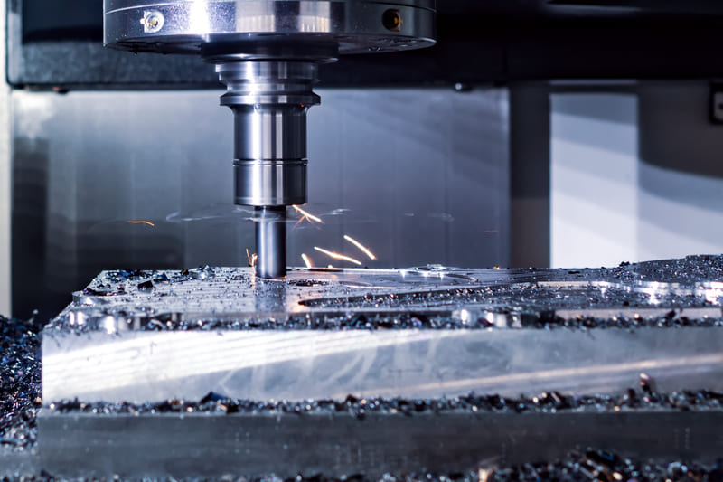
2. High-Speed Material Removal
When time is tight, I crank up the feed per tooth (fz) and increase cutting speed (Vc) on roughing passes. My 80 mm face mill can remove 3 mm of mild steel per pass—across 120 mm width—in seconds. Multiply that across a shift, and you’re looking at serious cycle time savings.
3. Adaptable Tooling for Every Job
I keep multiple face mills on hand—one with polished inserts for aluminum, another with negative rake TiAlN inserts for hardened steel. That flexibility means I can switch materials without retooling the entire setup. Insert coatings like TiCN and DLC also let me tackle more abrasive or heat-sensitive materials.
4. Roughing and Finishing in One Workflow
In many jobs, I’ll use the same face mill with a deeper ap (depth of cut) for roughing, then reduce fz and ap for finishing. This reduces total tool changes, keeps part zero intact, and lowers the risk of tolerance stack-up.
5. Prolonged Tool Life = Cost Savings
When you compare face milling to end milling, you’ll notice how evenly distributed the cutting forces are. This spreads the wear across multiple inserts, which I rotate individually. That means less frequent insert purchases and fewer scrapped parts due to chipped cutters.
Summary of Why It Matters
- Need precision? Face milling guarantees dimensional flatness.
- Need speed? Its high MRR boosts throughput without quality loss.
- Need flexibility? It adapts to almost any material or surface requirement.
- Need efficiency? Dual-purpose use and longer tool life keep overhead low.
Final Thought
Face milling might seem like a basic operation, but in my experience, it’s a powerhouse that underpins the success of more complex machining processes. When dialed in correctly, it becomes the foundation of a job well done—whether I’m prepping a mold cavity or squaring off a raw billet for aerospace.
Challenges & Pro Tips
Face milling offers incredible versatility, but it’s not without its pitfalls.
Over the years, I’ve faced my fair share of issues while face milling—chatter that ruins surface finish, inserts wearing out too fast, or thermal distortion affecting tolerances. These are common challenges, but with the right strategies, they’re entirely manageable. Here’s a practical breakdown of the most frequent problems and my proven workarounds.
If you’re experiencing surface issues or excessive tool wear, this section will help you troubleshoot faster and get better results every time you hit cycle start.
Common Face Milling Problems & How to Solve Them
| Challenge | Cause | Pro Tip |
|---|---|---|
| Chatter & Vibration | Unsupported workpiece, excessive tool overhang, or wide width of cut | Use a rigid setup, reduce axial and radial depths, and fine-tune spindle speed |
| Insert Wear or Breakage | Wrong insert geometry or grade, dry cutting, high temperature | Use coated inserts (TiAlN, TiCN), apply coolant, and lower cutting speed |
| Thermal Deformation | Long machining cycles without proper cooling or intermittent contact | Use flood coolant or MQL (minimum quantity lubrication) and reduce cycle time |
| Poor Surface Finish | Worn inserts, incorrect feed rate, or vibrations | Use a finishing pass with new inserts, low feed per tooth, and shallow depth |
| Entry Shock | Plunging directly into material causes impact loads | Program a ramp-in move or use a lead-in arc to reduce stress on inserts |
Dive Deeper: How to Fix Face Milling Issues Before They Happen
1. Minimize Chatter with Smart Fixturing
In my shop, I always double-check that parts are fully supported and clamped tight. I also try to match the tool’s diameter to be slightly wider than the surface width, which reduces the need for overlapping passes. If chatter starts mid-cut, I may drop the spindle speed by 10–15% or try a different insert geometry (positive rake tends to chatter less).

2. Prevent Premature Insert Wear
One common mistake is running dry on steel or stainless. That’s a fast way to cook your inserts. I always engage coolant unless I’m working aluminum, in which case I use a light mist. Also, using an insert grade that matches your material hardness helps extend tool life significantly. When I work with hardened steels, I upgrade to tougher carbide grades with TiAlN coating.
3. Handle Heat with Care
If you’re running a long face milling operation without coolant, expect thermal expansion to distort your part. I’ve had aluminum plates warp by up to 0.3 mm from heat buildup alone. To avoid this, I program pauses between passes or add MQL to keep temperatures down without creating a flood mess.
4. Finish Like a Pro
For cosmetic surfaces, I run a final pass with no more than 0.2 mm depth and a slow feed rate (sometimes under 0.05 mm/tooth). This removes tool marks from previous roughing passes and gives me the clean finish I need for client-facing parts.
5. Don’t Crash Into the Cut
Hard starts are hard on tools. Rather than dropping the cutter straight onto the surface, I use a lead-in move—usually a ramp or shallow arc. This gradually engages the insert, reducing shock and extending its life. Most CAM systems support this with a few extra clicks.
Extra Tips from the Floor
- Keep your inserts sharp — swap them out before they dull completely.
- Balance the cutter — especially if you’re using fly cutters or large-diameter tools.
- Use shorter tool holders — they’re more rigid and reduce deflection.
- Always run a test pass — especially when using new materials or insert geometries.
Final Thought
Face milling isn’t hard, but it is unforgiving when setup or parameters are off. I’ve learned that a bit of proactive tuning—choosing the right insert, dialing in feeds and speeds, and planning toolpaths—makes a world of difference. Once you’ve optimized your process, face milling becomes one of the most rewarding operations in your CNC arsenal.
Common Applications of Face Milling
Flat surfaces are essential for fit, alignment, and precision—face milling makes them happen.
Face milling is the unsung hero behind nearly every clean, flat component surface in modern manufacturing. From aerospace brackets to mold plates, it’s often the very first step in transforming raw material into a functional part. I’ve used face milling for everything from leveling stock for five-axis setups to prepping reference planes for boring tight-tolerance holes. Here’s where and why it’s indispensable.
Whether you’re working on heavy-duty castings or fine aluminum plates, you’ll find face milling at the core of your process chain—often multiple times across a single part.
Industry-Specific Applications of Face Milling
| Industry | Common Use Cases |
|---|---|
| Automotive | Surface leveling of engine blocks, cylinder heads, transmission housings |
| Aerospace | Machining flat reference faces on brackets, structural components, and titanium plates |
| Tool & Die | Flattening die plates and mold bases to prepare for cavity or core machining |
| Medical Equipment | Surface prep for stainless steel fixtures and biocompatible implant prototypes |
| Heavy Equipment | Removing scale and flattening bearing surfaces on cast iron housings and gearboxes |
Dive Deeper: How Face Milling Powers Real-World Machining
1. Datum Surface Creation
In precision machining, everything begins with a datum. One of the first steps I take when starting on a new billet or rough casting is milling a clean, flat surface. This not only gives me a trustworthy reference point for future operations, but it also helps align the part correctly in my fixture or vise. Especially in aerospace and die manufacturing, a stable, square surface is a non-negotiable requirement.
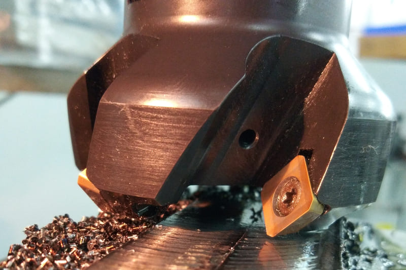
2. Prepping Castings and Forgings
Face milling is my go-to method for removing surface scale and warpage from raw cast or forged blanks. This is critical in industries like heavy equipment, where components arrive in less-than-perfect form. A deep pass with a sturdy face mill cleans up the scale and ensures the next operation won’t be fighting against distorted geometry.
3. Leveling for Surface Treatments
Before anodizing or coating a part, I often run a shallow finishing pass to ensure uniform surface height. Coating thickness can vary on uneven parts, so a smooth, consistent surface ensures better cosmetic and functional results. I do this often with aluminum enclosures and medical device parts.
4. Mold and Die Base Flattening
In mold making, base plates must be as flat as possible to support the precise geometry of cores and cavities. I use fly cutters or large-diameter face mills to get flatness down to 0.01 mm on steel and aluminum blocks. These setups take time, but the downstream precision benefits are huge.

5. CNC Setup Standardization
For parts that require multiple fixturing positions, face milling ensures each face rests squarely in the next setup. It’s a crucial step in multi-operation workflows, especially when working with irregular blanks or when flipping the part for six-sided machining.
Pro Tip: Use Face Milling Strategically in Your Workflow
- First operation strategy: Make the first face milled your master datum.
- Between ops: If you rough mill, then let the part cool before finishing the face to final tolerance.
- Post-heat-treatment: Use finishing passes to bring surfaces back to spec after distortion.
Final Thought
Face milling is more than just flattening—it’s about setting up every operation that follows for success. I’ve seen jobs go sideways from skipping this step or not giving it the attention it deserves. But when done right, it creates the strong, accurate foundation every precision part needs.
Best Practices for Effective Face Milling
Inconsistent finishes or tool wear issues? These face milling best practices can dramatically improve your results.
Face milling seems straightforward, but getting great results takes more than just setting feeds and speeds. Over the years, I’ve refined a set of repeatable techniques that help ensure consistent surface finish, minimal tool wear, and rock-solid accuracy. Here’s what really makes a difference when you’re trying to face mill with confidence.
Whether you’re working on aluminum castings or hardened steel blocks, applying the right setup strategy and machining tactics is the key to maximizing productivity and part quality.
Top Face Milling Techniques That Work
Match Tool Diameter to Surface Width
The best cutter for the job is one that’s slightly larger than the surface you want to machine. I typically choose a face mill 1.5 to 2 times the width of the surface. This ensures clean edge-to-edge coverage in fewer passes and minimizes tool marks at overlaps. For narrow parts or pocketed areas, I’ll use smaller shell mills or even finishing end mills for better accessibility.

Select the Right Insert Geometry
Not all inserts are created equal. When I’m working with aluminum or softer materials, I go with positive rake inserts—they reduce cutting forces and improve finish. For harder steels, I shift to negative rake inserts for better durability. Coatings like TiAlN or TiCN are a must if you’re running dry or at high speeds. Always use sharp inserts—dull ones chatter and leave streaks.
Plan Strategic Entry & Exit Moves
One of the biggest causes of insert damage is poor entry. Plunging straight into the workpiece edge with a face mill often leads to chipped inserts and poor finish. I ramp in whenever possible—this gently engages the cutter and avoids shock loading. When space is tight, I use lead-in and lead-out arcs in my CAM program to reduce impact at the beginning and end of the cut.
Minimize Interrupted Cuts
Nothing wears out tools faster than interrupted contact. I avoid face milling over slots, large holes, or part gaps if I can help it. If unavoidable, I reduce feed rates just before the interruption and ramp them back up once the cutter re-engages. Consistent contact equals longer tool life and better finishes.
Clamp and Fixture Rigidly
This seems obvious, but it’s one of the most common causes of face milling issues. Any part movement leads to chatter, uneven finish, or even catastrophic tool crashes. I always check for solid clamping across the entire face—especially for large plates. If necessary, I’ll use vacuum fixtures or modular clamping systems to reduce vibration and lift.
Bonus Tips for Tight Tolerances
- Use Fine Finishing Passes: A final light cut (~0.1 mm depth, slow feed) significantly improves surface quality.
- Coolant is Your Friend: Especially in steel and stainless steel. Helps prevent workpiece warping and extends insert life.
- Check Machine Leveling: For large flat parts, ensure your machine is square and tram is within spec.
- Monitor Tool Runout: Even 0.01 mm of runout on large cutters can cause vibration and uneven wear.
Face Milling Best Practices Checklist
| Practice | Benefit |
|---|---|
| Use optimal cutter diameter | Reduces passes and tool marks |
| Select appropriate insert grade | Improves finish and insert life |
| Use ramp-in entries | Prevents edge chipping and thermal shock |
| Minimize interrupted paths | Maintains smooth cutting and wear consistency |
| Apply tight clamping strategy | Eliminates vibration and deflection |
Final Thought
Face milling is a process where small mistakes become big problems fast. But when you apply these best practices—dialing in your entry strategy, tool selection, and clamping—you’ll see better surface finishes, longer tool life, and fewer surprises during production. I’ve learned to treat face milling as both an art and a science—and the payoff is always worth the effort.
Face Milling vs End Milling: What’s the Difference?
Confused about which milling method to use for your part? You’re not alone—understanding when to use face milling versus end milling is critical for surface finish, efficiency, and geometry.
Face milling and end milling may use similar CNC equipment, but they serve very different purposes in part production. I’ve used both methods extensively—each offers unique benefits depending on material, geometry, and machining goals. Let’s break them down in detail.
To optimize your machining process, you need to know the strengths and limitations of both. Here’s how they compare and when to choose one over the other.
Understanding the Key Differences
| Feature | Face Milling | End Milling |
|---|---|---|
| Cutting Surface | Bottom of the tool (face) | Side of the tool (edge) |
| Purpose | Creating flat surfaces or reference planes | Cutting slots, pockets, profiles, and contours |
| Tool Diameter | Typically large (50–160 mm) | Typically smaller (3–20 mm) |
| Surface Finish | Superior on large flat areas | Good on features, but may require finishing |
| Material Removal Rate | High for flat surfaces | Lower, more controlled for detail work |
| Tool Types | Face mills, shell mills, fly cutters | End mills (flat, ball nose, corner radius) |
| Chip Evacuation | Excellent—chips fly away from surface | More prone to re-cutting if pockets are deep |
When Should I Use Face Milling?
If your goal is to flatten a large surface quickly and precisely, face milling is your go-to. I use it regularly at the beginning of a machining cycle to prepare a datum or clean up castings. The large cutter diameter combined with multiple inserts allows fast material removal and excellent surface finish. It’s especially ideal for leveling mold bases, fixture plates, and structural housings.
When Should I Use End Milling?
End milling is for everything else—slots, pockets, fillets, complex contours, and 3D shapes. When I need tight feature tolerances or internal corners, end mills offer the precision and control required. Flat end mills are great for finishing planar faces on small parts, while ball end mills are perfect for contoured surfaces and sculpted geometries like impellers or molds.

Toolpath Strategies: Face vs End Milling
Face Milling:
- Use parallel linear passes with 50–70% step-over
- Engage with a ramp or lead-in to avoid edge damage
- Use higher feeds and shallow depths for finish passes
End Milling:
- Use trochoidal or adaptive toolpaths for deep cuts
- Apply climb milling for better finish and tool life
- Vary depth of cut to reduce tool wear on long runs
Combining Both Methods for Best Results
On many parts, I use both processes together. For example, I’ll start by face milling the top surface to ensure flatness, then switch to end mills to create pockets, threaded holes, or bosses. This combination approach gives me precision where needed, and speed where possible. It’s all about matching the tool to the feature.
Final Verdict
Face milling and end milling are complementary—not competing—processes. Face milling is ideal for flat, broad surfaces, while end milling offers precision for complex or detailed features. By understanding the differences and aligning them with your part geometry, you’ll save time, reduce tool wear, and improve overall quality.
Over the years, I’ve learned that knowing when to switch from one method to the other is just as important as tool choice or spindle speed. Make smart decisions based on geometry—and let each process do what it does best.
Conclusion
Face milling is a foundational CNC machining technique that combines efficiency with precision. While often underestimated, its ability to deliver ultra-flat surfaces and dimensional stability makes it indispensable across industries.
In my own experience working on everything from aerospace brackets to mold bases, I’ve seen firsthand how optimized face milling setups can transform surface quality and reduce downstream processing. Choosing the right tool geometry, applying stable fixturing, and tuning your feeds and speeds aren’t just technical choices—they’re what differentiate a good shop from a great one.
To recap:
- Face milling excels at removing material quickly while achieving superior surface finishes.
- Proper cutter selection—diameter, insert geometry, coatings—has a major impact on results.
- Material-specific parameters and rigid setups are key to reducing chatter and prolonging tool life.
- This operation is widely used in industries like automotive, aerospace, medical, and heavy equipment manufacturing.
So, whether you’re prepping a part for tight-tolerance drilling or creating a flawless aesthetic surface, face milling should be in your CNC playbook. Mastering it isn’t just about knowing the numbers—it’s about building a process that works every time, for every part.
And if you’re looking to outsource precision face milling, Onlyindustries delivers consistent, production-ready results with expert engineering support and rapid lead times. Let’s build something flat and flawless—together.
Need Face Milling for Your Next Project?
Struggling to find a reliable solution for ultra-flat surfaces and tight-tolerance machining?
Face milling isn’t just about removing material—it’s about delivering precision, consistency, and performance on every part. If you’re working with castings, billet metals, or custom components that require exceptional surface finish and planarity, choosing the right manufacturing partner is critical.
Why Onlyindustries Is the Right Choice
I’ve collaborated with enough suppliers to know that not all CNC shops are created equal. At Onlyindustries, we specialize in CNC face milling that meets demanding industry standards—from aerospace-grade aluminum to hardened tool steels. Here’s what sets us apart:
| Feature | What You Get |
|---|---|
| Engineering-Led Workflow | DFM feedback, toolpath simulation, and post-process QA |
| Material Versatility | Expertise in aluminum, steel, titanium, plastics, and composites |
| Surface Finish Excellence | Achieve Ra ≤ 0.8 μm with optimized feed and tool paths |
| Rapid Lead Times | Prototypes in 10–15 days, production in 20–30 days |
| Flexible MOQs | Start from 1 unit—no tooling required |
Industries We Serve
- Aerospace: Titanium mounting plates, datums, frame components
- Automotive: Cylinder heads, engine brackets, transmission casings
- Medical Devices: Surgical housings, prosthetic interfaces
- Industrial Machinery: Base plates, actuator blocks, bearing surfaces
Let’s Get Started
We’re more than just a machine shop—we’re your manufacturing partner. Whether you’re validating a design or scaling up production, our team ensures you receive face milled parts that meet both dimensional specs and surface standards.
Ready to quote or just exploring options? Contact us now to discuss your face milling requirements. You’ll get transparent pricing, fast DFM feedback, and machining that exceeds expectations.