Skip to content
 Welding is a cornerstone of industries like construction, shipbuilding, automotive, and aerospace. A strong, defect-free weld is critical to structural integrity, safety, and product life. But even experienced welders can encounter defects if process parameters, materials, or techniques are off.
This guide explores 16 common welding defects—what they look like, why they happen, and how to prevent them.
Porosity – What Is It and How Do You Prevent It?
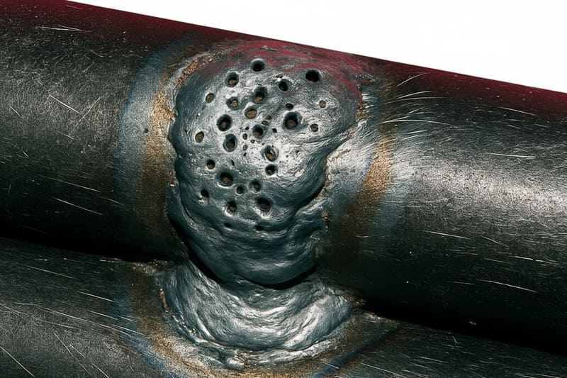
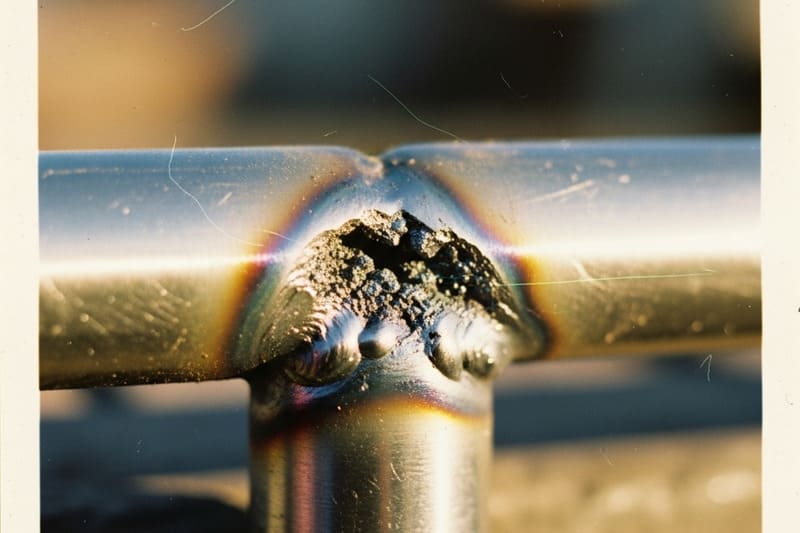
Porosity in welding is a hidden enemy that compromises both strength and appearance. It occurs when trapped gas forms small cavities inside the weld metal, reducing the joint’s load-bearing capacity.
In short: Porosity is caused by contaminants or poor shielding, and can be avoided with clean materials, proper gas flow, and correct storage of consumables.
Understanding the Problem
When molten weld metal solidifies, any gas trapped inside forms pores or bubbles. These pores can be visible on the surface or hidden within the weld. While a few small pores may be acceptable in non-critical welds, structural and pressure-retaining applications often have zero-tolerance policies for porosity.
Types of Porosity
- Surface Porosity: Clearly visible pits on the weld surface.
- Subsurface Porosity: Hidden cavities detected through X-ray or ultrasonic testing.
- Cluster Porosity: Groups of pores concentrated in one area, indicating severe contamination.
- Wormhole Porosity: Long, tubular cavities formed by trapped gas escaping during solidification.
Main Causes
| Cause | Explanation |
|---|---|
| Base Metal Contamination | Oil, grease, paint, rust, or moisture on the workpiece release gas when heated. |
| Excessive Shielding Gas Flow | High flow rates cause turbulence, pulling air into the arc. |
| Poor Electrode Storage | Moisture absorption by flux-coated electrodes releases hydrogen into the weld pool. |
| Improper Welding Technique | Incorrect torch angle or arc length can disrupt gas coverage. |
Prevention Methods
- Thoroughly clean base metal with a grinder, wire brush, or solvent before welding.
- Set shielding gas flow within manufacturer-recommended limits (typically 15–25 CFH for MIG).
- Store electrodes and filler rods in a dry oven or sealed container.
- Maintain correct torch angle and short arc length to maximize gas shielding efficiency.
Inspection & Quality Control
Porosity detection methods include visual inspection, dye penetrant testing, X-ray inspection, and ultrasonic testing. For high-integrity welds—such as in aerospace or pressure vessels—non-destructive testing (NDT) is mandatory to ensure no hidden gas pockets remain.
Real-World Example
In pipeline welding, even minor porosity can lead to leaks under pressure. A well-known case in the oil and gas industry involved costly repairs and downtime because electrodes were left exposed to humid air overnight, leading to hydrogen-induced porosity.
By enforcing strict consumable storage policies and proper pre-weld cleaning, that same company reduced porosity-related rework by over 90%.
Incomplete Fusion – Causes, Effects, and Prevention
Incomplete fusion is one of the most critical welding defects because it directly reduces the joint’s mechanical strength. It occurs when the weld metal fails to fuse completely with the base metal or with a previous weld pass.
In short: Incomplete fusion is caused by insufficient heat, poor joint preparation, or incorrect torch technique, and can be avoided with proper heat settings, beveling, and travel angles.
Understanding the Problem
During welding, molten filler metal must melt and bond with the surfaces it contacts. If the base metal or previous weld pass remains unmelted due to incorrect parameters or poor preparation, the resulting joint will have areas of mechanical weakness, often invisible to the naked eye until failure occurs under load.
Common Types of Incomplete Fusion
- Sidewall Fusion Failure: Weld bead does not bond with the joint’s vertical surfaces.
- Interpass Fusion Failure: New weld pass does not fuse with the previous layer.
- Root Fusion Failure: Molten metal fails to penetrate and bond at the joint root.
Main Causes
| Cause | Explanation |
|---|---|
| Low Heat Input | Insufficient current or voltage prevents melting of the base metal. |
| Poor Joint Preparation | Improper beveling, small root gaps, or residual contaminants block fusion. |
| Incorrect Torch Angle | Arc fails to direct enough energy toward the fusion zone. |
| Excessive Travel Speed | Arc moves too quickly to melt base material fully. |
Prevention Methods
- Increase welding current and voltage according to material thickness and process specifications.
- Properly prepare joints by beveling edges and cleaning surfaces to bare metal.
- Use the correct torch or electrode angle (typically 5–15° push or drag depending on process).
- Adjust travel speed to allow complete melting without excessive heat input.
Inspection & Detection
Incomplete fusion can be detected through destructive testing (bend tests, macro-etching) or non-destructive testing (ultrasonic testing, radiography). UT is especially effective at identifying sidewall or interpass fusion issues that are hidden from view.
Real-World Example
In shipbuilding, incomplete fusion in hull welds has led to structural failures in heavy seas. After an incident, the investigation revealed inadequate bevel preparation and too-low amperage settings on thick plate welds. By introducing stricter fit-up inspections and parameter monitoring, the shipyard drastically reduced incomplete fusion occurrences.
Incomplete Penetration – Causes, Risks, and Solutions
Incomplete penetration is a welding defect where the weld metal does not extend fully through the joint’s thickness. This leaves an unfilled gap at the root, significantly weakening the joint’s load-bearing capacity.
In short: Incomplete penetration happens when heat, root gap, or travel speed are not optimized, and it can be avoided with correct current settings, proper joint preparation, and controlled travel.
Why It Matters
The strength of a welded joint depends on the metal fusing completely from one side to the other. When penetration is incomplete, stress concentrations form at the unbonded root area. Under cyclic loading, these can initiate cracks that propagate and cause catastrophic failure — particularly dangerous in pressure vessels, pipelines, and load-bearing structures.
Common Causes
| Cause | Effect on Weld |
|---|---|
| Tight Root Gap | Restricts molten metal flow, preventing complete root fusion. |
| Low Welding Current | Insufficient heat fails to melt the joint root fully. |
| High Travel Speed | Arc moves too quickly, not allowing enough time for root fusion. |
| Poor Joint Fit-Up | Misalignment or uneven gaps lead to incomplete bonding. |
Prevention Methods
- Set welding current and voltage according to material thickness and process requirements.
- Ensure proper root gap (typically 1.5–3 mm for many processes) for adequate penetration.
- Maintain steady travel speed to allow molten metal to reach and bond at the root.
- Use back-gouging or double-sided welding for thicker sections to guarantee full penetration.
- Employ proper joint preparation, ensuring alignment and consistent fit-up.
Detection Methods
Incomplete penetration is often hidden inside the joint and cannot be spotted visually. Non-destructive testing (NDT) methods such as ultrasonic testing (UT) and radiographic testing (RT) are effective in identifying unbonded root areas before the part is put into service.
Real-World Example
In pipeline welding, incomplete penetration is a major rejection cause during hydrostatic testing. A gas transmission company reduced defects by introducing strict root gap checks, using root passes with higher current, and employing internal weld backing rings where appropriate.
Undercut – Causes, Risks, and Solutions
Undercut is a groove melted into the base metal along the weld toe that is not filled with weld metal. This defect reduces the cross-sectional thickness of the base metal and acts as a stress riser, which can significantly weaken the joint.
In short: Undercut occurs when excessive heat, high travel speed, or improper torch angle causes the molten metal to wash away base material without adequate fill.
Why It Matters
Undercut compromises the structural integrity of the joint by creating a sharp notch at the weld edge. This notch concentrates stress and can be the starting point for fatigue cracks, especially in dynamic load applications like cranes, bridges, and pressure vessels.
Common Causes
| Cause | Effect on Weld |
|---|---|
| Excessive Welding Current | Overheats the base metal, causing it to melt away too quickly. |
| High Travel Speed | Prevents molten filler metal from filling the groove at the weld toe. |
| Incorrect Torch/Electrode Angle | Directs heat away from filler deposition into the base metal edge. |
| Poor Weaving Technique | Overextending the arc to the edges leads to metal washout. |
Prevention Methods
- Reduce welding current to match material thickness and joint type.
- Lower travel speed to allow proper filler deposition at the edges.
- Maintain a correct torch or electrode angle (usually 5–15° from vertical in the travel direction).
- Use controlled weaving or stringer beads to avoid overheating the base metal edges.
- Ensure proper fit-up and avoid forcing excessive heat into thin edges.
Detection Methods
Undercut is often visible to the naked eye during visual inspection. However, in critical applications, a magnified inspection or dye penetrant testing (PT) can be used to detect fine grooves that might not be easily seen but could still compromise strength.
Real-World Example
In shipbuilding, undercut along deck welds has been known to lead to premature cracking due to wave-induced stress. A major shipyard reduced undercut occurrences by retraining welders on torch angles and implementing strict parameter controls for welding current and travel speed.
Overlap – Causes, Risks, and Solutions
Overlap is a welding defect where molten weld metal flows over the base metal surface without fusing to it. This creates a protruding edge that can trap contaminants, act as a stress riser, and reduce joint strength.

In short: Overlap happens when excess filler metal is deposited but fails to bond with the base metal, often due to improper technique or parameter settings.
Why It Matters
Overlap not only weakens the weld but can also be a starting point for fatigue cracks, especially in load-bearing structures. The protruding lip can interfere with part fit-up, sealing surfaces, or create turbulence in fluid-handling components.
Common Causes
| Cause | Effect on Weld |
|---|---|
| Low Travel Speed | Causes excessive deposition that spills over without proper fusion. |
| Excessive Heat Input | Makes the molten pool too fluid, allowing it to run over the edges. |
| Incorrect Torch/Electrode Angle | Directs molten metal away from the joint, preventing proper bonding. |
| Too Large Electrode or Filler Diameter | Deposits more metal than the joint can accommodate at one time. |
Prevention Methods
- Increase travel speed to ensure molten metal solidifies within the joint.
- Match welding current and voltage to material thickness and joint design.
- Maintain a proper torch or electrode angle to keep the arc focused on the joint root.
- Use an appropriate filler metal diameter for the joint size.
- Avoid weaving too widely; keep passes within the joint boundaries.
Detection Methods
Overlap is usually visible during visual inspection as a bead lip extending beyond the weld toe. For critical applications, dye penetrant testing (PT) can confirm whether the overlap area has fused properly or remains an unfused overhang.
Real-World Example
In pipeline welding, overlap inside the pipe can cause flow restriction and increase turbulence, leading to erosion and failure over time. A gas transmission company reduced overlap incidents by enforcing maximum bead width specifications and retraining welders on travel speed control.
Slag Inclusions – Causes, Risks, and Solutions
Slag inclusions are nonmetallic deposits trapped inside the weld metal. They occur when flux residue from welding consumables or previous passes fails to float to the weld surface and solidifies within the joint.
In short: Slag inclusions compromise weld integrity by creating weak points and stress concentration zones inside the joint.
Why It Matters
Slag inclusions reduce the mechanical strength of a weld and act as crack initiation points under load. In high-pressure or structural applications, even small inclusions can lead to catastrophic failures over time. They also fail many industry quality standards, requiring costly rework.
Common Causes
| Cause | Effect on Weld |
|---|---|
| Inadequate Slag Removal Between Passes | Traps old slag in subsequent weld layers. |
| Poor Torch or Electrode Manipulation | Improper weaving prevents slag from floating out of the molten pool. |
| Low Heat Input | Slag solidifies before rising to the surface. |
| Incorrect Welding Position | Some positions make slag escape more difficult. |
Prevention Methods
- Thoroughly clean slag from each pass before adding the next layer using a chipping hammer and wire brush.
- Increase heat input slightly to allow slag to rise to the surface.
- Use proper weaving and travel speed to encourage slag flow out of the molten pool.
- Select the correct electrode type and size for the position and joint type.
- Maintain consistent arc length to control bead shape and slag removal.
Detection Methods
While large slag inclusions may be visible on the surface after grinding, smaller internal inclusions require non-destructive testing (NDT) methods such as radiographic testing (RT) or ultrasonic testing (UT) to detect and size the defect accurately.
Real-World Example
In shipbuilding, slag inclusions in hull welds can lead to water ingress and structural failure. A major shipyard reduced slag-related repairs by implementing a “clean-as-you-go” policy, requiring welders to remove slag immediately after each pass before starting the next one.
Cracks (Hot & Cold) – Causes, Risks, and Solutions
Cracks in welds are linear fractures that can occur either during solidification (hot cracks) or after cooling to ambient temperature (cold cracks). They are among the most severe welding defects because they directly compromise structural integrity.

In short: Cracks act as immediate points of failure, propagating under stress and often leading to sudden, catastrophic part failure.
Why It Matters
Unlike other welding defects that may be tolerated to some degree, cracks are unacceptable in almost all engineering codes and standards (e.g., AWS D1.1, ASME Section IX). They create sharp stress concentrators that accelerate fatigue failure, making them a critical safety hazard in load-bearing and pressure-retaining components.
Types of Welding Cracks
| Type | When It Occurs | Typical Cause |
|---|---|---|
| Hot Cracks | During solidification, while weld metal is still above ~1,000°C | Excessive shrinkage, segregation of impurities, poor joint design |
| Cold Cracks | After cooling to room temperature, often hours later | Hydrogen embrittlement, residual stress, hard microstructures |
Common Causes
- Excessive residual stress from poor joint restraint or welding sequence
- Improper preheat or post-weld heat treatment (PWHT)
- High levels of sulfur, phosphorus, or other impurities in the base metal
- Rapid cooling rates leading to brittle microstructures (e.g., martensite)
- Moisture-contaminated consumables introducing hydrogen into the weld
Prevention Methods
- For Hot Cracks: Optimize joint design to allow for shrinkage, use proper filler metal composition, and control heat input to reduce thermal stress.
- For Cold Cracks: Preheat base metals, maintain interpass temperatures, use low-hydrogen electrodes, and perform PWHT when required.
- Store consumables in heated, dry conditions to prevent hydrogen pickup.
- Sequence welds to balance stresses and avoid over-restraining the joint.
Detection Methods
Surface cracks can often be detected visually, but subsurface cracks require non-destructive testing such as Magnetic Particle Testing (MT), Dye Penetrant Testing (PT), or Ultrasonic Testing (UT). Radiographic Testing (RT) is also effective for certain weld configurations.
Real-World Example
In a pressure vessel manufacturing facility, cold cracks appeared 24 hours after welding due to insufficient preheating of thick carbon steel plates. After implementing a 150°C preheat protocol and switching to low-hydrogen electrodes, the defect rate dropped to zero.
Burn-Through – Causes, Risks, and Prevention
Burn-through is a welding defect where excessive heat input melts completely through the base metal, creating holes in the weld area. This defect not only weakens the joint but also often requires costly rework or part replacement.
In short: Burn-through happens when your heat control is off, your joint fit-up is too loose, or your travel speed is too slow—causing the weld pool to collapse through the workpiece.
Why It Matters
Burn-through is more than an aesthetic flaw—it can render a weld unusable. In pressure-retaining equipment, piping, or thin sheet structures, even a small burn-through can cause leakage, reduce load capacity, and fail inspection standards such as AWS D1.1, ASME Section IX, or ISO 5817.
Common Causes
- Excessive heat input from high amperage or voltage settings
- Large root gap between joint members, increasing molten pool instability
- Slow travel speed, allowing prolonged heat exposure to one area
- Thin base metal with no heat control adjustments
- Poor joint preparation or incorrect welding process for material thickness
Prevention Methods
- Reduce welding current and/or voltage to match material thickness.
- Close root gaps to an acceptable range—typically 1.5 mm or less for thin sheet metals.
- Increase travel speed to avoid overheating any single spot.
- Use backing bars, chill plates, or copper backing strips for thin materials to dissipate heat.
- Select appropriate welding processes—such as pulsed MIG or TIG—for thin sections.
- Perform test welds to verify parameter suitability before full production.
Detection Methods
Burn-through is usually visible to the naked eye as holes or melt-through zones, but when hidden behind assemblies or in tubular structures, borescope inspection or radiographic testing (RT) may be needed for quality verification.
Real-World Example
In an HVAC ducting project, operators experienced frequent burn-through on thin galvanized sheets during MIG welding. By switching to a pulsed MIG setup, reducing current by 20%, and using copper backing bars, the team completely eliminated burn-through defects without slowing production speed.
Spatter – Causes, Impact, and Control Strategies
Spatter refers to small droplets of molten metal that are expelled from the welding arc and land on the surrounding surface. While it usually doesn’t compromise structural strength, it affects appearance, increases cleanup time, and can cause surface contamination.
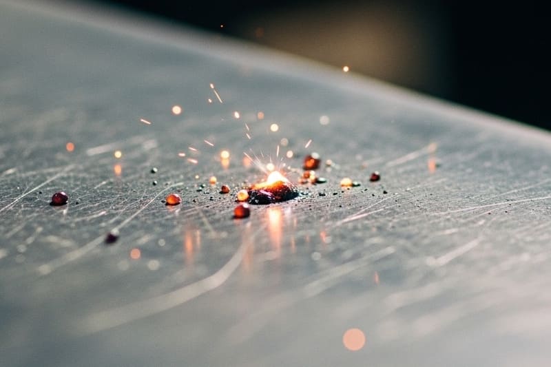
In short: Spatter is a symptom of imbalanced welding parameters, poor shielding gas control, or incorrect technique—leading to unnecessary post-weld finishing work.
Why It Matters
Excessive spatter increases production costs due to extra grinding, chipping, or blasting required for cleanup. In some industries—such as automotive or consumer products—visible spatter is unacceptable and can cause rejections during quality inspections.
Common Causes
- Excessive welding current producing unstable arcs and molten droplet ejection.
- Incorrect polarity for the welding process (e.g., DCEP vs. DCEN).
- Poor shielding gas composition or contaminated gas supply.
- Improper stick-out length, causing inconsistent arc stability.
- Dirty or oily base material leading to arc disturbances.
Prevention Methods
- Optimize current and voltage settings based on electrode size and material thickness.
- Use the correct polarity recommended for the welding process and electrode type.
- Select a suitable shielding gas—e.g., 75% Argon / 25% CO₂ for GMAW—to stabilize the arc.
- Maintain a consistent stick-out length to ensure smooth arc transfer.
- Clean the base metal thoroughly before welding to remove rust, oil, and paint.
- Consider using anti-spatter spray to protect adjacent surfaces in high-spatter processes.
Detection Methods
Spatter is visually identifiable as small, rough metallic beads near the weld bead. In production lines where finishing is minimal, excessive spatter is flagged during visual inspection as a surface defect requiring rework.
Real-World Example
In a structural steel fabrication shop, operators using CO₂ shielding gas saw heavy spatter on beam joints. By switching to a mixed gas blend (80% Argon / 20% CO₂) and fine-tuning voltage settings, spatter was reduced by over 70%, cutting cleanup time in half and improving overall workflow efficiency.
Distortion – Causes, Control, and Prevention in Welding
Distortion occurs when a welded component changes shape due to uneven heating and cooling cycles during the welding process. This warping can cause misalignment, assembly difficulties, or even structural weakness if not corrected.
In short: Distortion is the result of thermal stresses pulling or pushing the metal into an altered form—making dimensional control a critical challenge in fabrication.
Why It Matters
Excessive distortion increases rework costs, delays project timelines, and can lead to scrap if tolerances are exceeded. In precision industries like aerospace or pressure vessel fabrication, even minor distortion can render a part unusable.
Common Causes
- High heat input causing excessive thermal expansion and contraction.
- Improper welding sequence concentrating heat in one area without balance.
- Thin base materials that cannot resist thermal stress.
- Long weld beads without breaks or staggered patterns.
- Insufficient fixturing or clamping to restrain movement.
Prevention Methods
- Use the minimum heat input necessary to achieve sound fusion.
- Apply balanced welding sequences, such as backstep or skip welding, to spread heat evenly.
- Clamp and fixture parts securely to prevent movement during welding.
- Pre-plan joint design to minimize large weld volumes in one area.
- For thin materials, use intermittent welding instead of continuous beads when strength requirements allow.
- Employ preheating and controlled cooling when working with high-strength or alloy steels to reduce thermal shock.
Detection Methods
Distortion can be identified by visual inspection, straightedge checks, or dimensional measurements after cooling. For high-precision parts, coordinate measuring machines (CMMs) are often used to ensure geometry remains within tolerance.
Real-World Example
In a shipyard fabricating large steel panels, excessive distortion during welding led to gaps in assembly. By switching to a skip welding sequence and adding temporary stiffeners, distortion was reduced by 60%, cutting corrective grinding and bending time significantly.
Arc Strikes – Causes, Effects, and Prevention in Welding
Arc strikes occur when the welding arc accidentally touches the base metal outside the intended weld area. This creates localized melting, surface marks, or even microcracks in the material—often compromising structural integrity and aesthetics.

In short: Arc strikes are unintentional defects caused by poor arc control, and they can lead to material weaknesses, especially in high-stress applications.
Why It Matters
While an arc strike may appear to be just a surface blemish, it can alter the microstructure of the metal, creating a heat-affected zone (HAZ) where cracks may initiate. This is particularly critical in components subject to fatigue, pressure, or impact loads—such as pipelines, bridges, and aircraft structures.
Common Causes
- Poor arc initiation control by the welder.
- Starting the arc outside the weld joint instead of on the run-on tab or within the joint.
- Dragging the electrode across the base material during repositioning.
- Inadequate welder training or fatigue during long shifts.
Prevention Methods
- Always strike the arc within the weld zone or on designated run-on/run-off tabs.
- Use proper arc starting techniques—avoid scratching the electrode across the surface.
- Ensure good visibility of the joint before arc initiation.
- Train welders on consistent electrode handling and movement control.
- Use welding curtains or better lighting to improve arc positioning accuracy.
Repair and Remediation
- For carbon steel: Grind out the arc strike area, then blend and inspect.
- For high-strength or alloy steels: After grinding, perform magnetic particle inspection (MPI) or dye penetrant testing to confirm no cracking remains.
- In critical applications (e.g., pressure vessels), repair procedures must comply with ASME or AWS D1.1 standards.
Real-World Example
During the construction of a high-pressure pipeline, random arc strikes were found during inspection. The engineering team mandated rework by grinding and magnetic particle testing. They also implemented a strict policy of using run-on tabs for all weld starts, which reduced arc strike occurrences by over 90% in subsequent phases.
Excessive Reinforcement – Causes, Effects, and Prevention in Welding
Excessive reinforcement occurs when the deposited weld metal builds up too high above the surface of the joint. While some reinforcement is necessary for strength, too much can create stress concentration points, interfere with part fit-up, and fail inspection criteria under welding codes.
In short: Excessive reinforcement means the weld profile is overfilled, often due to over-deposition or slow travel speeds, and it can weaken the joint rather than strengthen it.
Why It Matters
An overly reinforced weld can disrupt load distribution across the joint and create stress risers that lead to cracking under cyclic loading. In piping or pressure vessel applications, excessive internal reinforcement may also restrict flow or cause turbulence, leading to erosion or corrosion over time.
Common Causes
- Slow travel speed causing excess filler metal deposition.
- Using a larger electrode or filler rod than required for the joint size.
- Poor heat control, allowing molten metal to pile up rather than fuse evenly.
- Failure to maintain correct torch or electrode angle, leading to uneven distribution.
Prevention Methods
- Set appropriate travel speed to avoid excessive metal buildup.
- Match filler metal size to the joint and welding procedure specification (WPS).
- Maintain the correct electrode angle—typically 5–15° for most processes.
- Control heat input to ensure good wetting of the weld toes without overfilling.
- Follow code requirements (e.g., AWS D1.1 or ASME Section IX) for allowable reinforcement height.
Repair and Remediation
- Grind the excess reinforcement flush with the specified profile.
- Perform post-repair inspection (visual and NDT if required) to confirm no defects were introduced.
- Update WPS parameters if repeated excessive reinforcement is observed in production.
Real-World Example
In a stainless-steel food processing pipeline project, several welds failed inspection for excessive internal reinforcement. The repair involved grinding and re-polishing the interior surfaces to meet sanitary standards. After adjusting the travel speed and filler wire feed rate, the welding team achieved consistent profiles that passed both sanitary and structural inspections.
Root Concavity – Understanding, Preventing, and Correcting This Welding Defect
Root concavity, sometimes called “suck-back,” is a depression or underfill at the root side of a weld joint. It occurs when molten weld metal contracts away from the root face during solidification, leaving a thin or recessed root bead.

In short: Root concavity reduces the effective throat thickness of the weld, compromising its load-bearing capacity and potentially leading to leaks in pressure-retaining structures.
Why It Matters
Even if the face of the weld appears sound, root concavity can drastically weaken the joint. In piping, tank fabrication, and structural steel, this defect can fail pressure tests, cause stress concentrations, and reduce fatigue life. Many industry codes, such as ASME Section IX and AWS D1.1, set strict limits or prohibitions on root concavity depth.
Common Causes
- Improper fit-up with too tight a root opening, restricting penetration and molten metal flow.
- Insufficient heat input, preventing complete fusion and fill at the root.
- Poor control of root pass travel speed, leading to uneven bead profile.
- Lack of proper backing gas in TIG welding, causing oxidation and poor root bead shape.
- Incorrect torch or electrode angle, pulling molten metal away from the root area.
Prevention Methods
- Ensure the root gap matches the Welding Procedure Specification (WPS)—often 1.5 to 3 mm depending on process and material.
- Use the correct heat input to fully penetrate and fill the root without excessive reinforcement.
- Maintain consistent travel speed and weave pattern to control bead profile.
- For GTAW (TIG) welding, use proper backing gas flow to protect the root bead from oxidation.
- Adjust electrode or torch angle to direct filler into the root area.
Repair and Remediation
- Back-gouge the root area to sound metal and re-weld to correct profile.
- Perform visual inspection and, if required, NDT methods such as radiography or ultrasonic testing to confirm defect removal.
- Revise the WPS parameters if the defect recurs frequently during production runs.
Real-World Example
During the fabrication of high-pressure steam piping, radiographic inspection revealed several joints with root concavity exceeding the ASME allowable limit. The team corrected these by back-gouging and rewelding with adjusted root opening and increased amperage. Subsequent inspections passed without defects, ensuring the piping met both structural and pressure-retention requirements.
Lack of Sidewall Fusion – Causes, Prevention, and Repair
Lack of sidewall fusion is a welding defect where the weld metal fails to properly bond with one or both sides of the joint’s groove walls. This creates unbonded regions that can act as crack initiation points under load.
In short: Even if the weld appears visually acceptable on the surface, poor sidewall fusion compromises structural integrity and can lead to premature failure in service.
Why It Matters
Sidewall fusion is critical to ensuring that the weld acts as a continuous, homogeneous structure with the base material. Lack of fusion reduces load transfer capability, increases stress concentration, and is often unacceptable under welding codes like AWS D1.1 or ASME Section IX. This defect is especially dangerous in high-pressure piping, structural steel frameworks, and critical aerospace or shipbuilding applications.
Common Causes
- Insufficient heat input – not enough energy to melt and fuse the groove walls.
- Improper torch/electrode angle – failing to direct heat and filler toward the groove sidewalls.
- Excessive travel speed – reducing the time available for sidewall melting and fusion.
- Incorrect joint preparation – groove angle too narrow, preventing proper torch access.
- Contamination (rust, oil, paint) on groove faces, inhibiting metallurgical bonding.
Prevention Methods
- Set correct current, voltage, and travel speed per the Welding Procedure Specification (WPS).
- Increase groove angle if accessibility to the sidewalls is restricted.
- Maintain proper torch or electrode angle to direct heat toward sidewalls during welding.
- Clean and grind groove faces before welding to remove oxides, mill scale, and contaminants.
- Use stringer beads or weaving techniques to ensure even sidewall melting.
Repair and Remediation
- Grind out defective weld areas to expose clean base material.
- Re-weld with adjusted parameters ensuring adequate fusion on both sidewalls.
- Perform visual inspection followed by NDT methods like ultrasonic testing or radiography to verify fusion quality.
Real-World Example
In offshore structural welding, ultrasonic testing detected lack of sidewall fusion in several tubular joint welds. The cause was traced to insufficient groove angle combined with a high travel speed. After modifying joint prep to a wider bevel and reducing travel speed, all subsequent welds passed inspection, meeting stringent offshore safety standards.
Wormholes – Causes, Prevention, and Repair
Wormholes are elongated gas pockets trapped within a weld bead, usually appearing as tunnel-like voids running along the weld’s length. Unlike round porosity, wormholes are directional and often indicate shielding or contamination problems during the weld process.

In short: Wormholes weaken weld integrity, disrupt load transfer, and can act as crack initiation sites, making them unacceptable under most welding codes.
Why It Matters
Because wormholes form within the weld metal, they are often not visible on the surface. If undetected, they can severely reduce mechanical strength, cause leaks in pressure-retaining systems, and compromise fatigue resistance. Industries such as aerospace, petrochemical, and shipbuilding treat wormholes as critical defects requiring immediate corrective action.
Common Causes
- Contaminated base metal – presence of oil, grease, paint, rust, or moisture introducing gas during fusion.
- Poor shielding gas coverage – turbulence, incorrect flow rates, or wind drafts disrupting protection.
- Excessive travel speed – trapping gases before they can escape from the molten pool.
- Incorrect electrode storage, leading to absorbed moisture releasing hydrogen during welding.
- Improper joint preparation leaving gaps or voids that trap gases.
Prevention Methods
- Thoroughly clean base metal surfaces using wire brushing, grinding, or solvent cleaning before welding.
- Check and maintain correct shielding gas type, flow rate, and nozzle condition.
- Shield the weld area from drafts or use screens to prevent gas disruption.
- Control travel speed to allow gas bubbles to escape from the molten pool before solidification.
- Store and handle electrodes and filler rods per manufacturer recommendations to prevent moisture absorption.
Repair and Remediation
- Grind out defective sections until sound metal is reached.
- Re-weld using corrected shielding gas and travel parameters.
- Perform non-destructive testing (NDT) such as radiographic or ultrasonic inspection to ensure the defect has been eliminated.
Real-World Example
During fabrication of a high-pressure steam header, radiographic inspection revealed multiple wormholes caused by a damaged gas nozzle producing inconsistent shielding. After replacing the nozzle and increasing pre-weld cleaning standards, defect rates dropped to zero, ensuring compliance with ASME Section IX quality requirements.
Overheating / HAZ Issues – Causes, Prevention, and Control
Overheating and Heat-Affected Zone (HAZ) issues occur when excessive thermal input during welding alters the metallurgical structure of the base metal adjacent to the weld. This can result in unwanted hardness, grain growth, brittleness, or residual stresses that compromise the part’s performance and longevity.
In short: Poor heat control can weaken the HAZ, making it prone to cracking, distortion, and premature failure under service conditions.
Why It Matters
The HAZ is often the weakest link in a welded joint because it undergoes significant thermal cycling without actually melting. Overheating this zone can lead to reduced toughness, embrittlement, and susceptibility to fatigue or corrosion. This is especially critical in industries like pressure vessel fabrication, aerospace, and pipeline welding where component failure can have catastrophic consequences.
Common Causes
- Excessive welding current or voltage – introduces more heat than the material can dissipate.
- Prolonged arc dwell time – lingering too long in one spot increases local temperature.
- Improper preheating or post-weld heat treatment practices.
- Incorrect filler material creating metallurgical incompatibility in the HAZ.
- Lack of interpass temperature control in multi-pass welds.
Prevention Methods
- Use proper welding parameters (current, voltage, travel speed) matched to the material and joint type.
- Apply controlled preheating to reduce thermal gradients without overheating.
- Limit interpass temperature to avoid cumulative heat buildup in the HAZ.
- Select filler metals compatible with the base material to minimize adverse metallurgical changes.
- Implement post-weld heat treatment (PWHT) when required by codes or material specifications.
Repair and Remediation
- Remove and replace overheated sections where metallurgical properties have degraded beyond acceptable limits.
- Conduct hardness testing and microstructural analysis to assess HAZ integrity.
- Use controlled grinding and re-welding with adjusted parameters to restore joint quality.
Real-World Example
In a refinery piping project, repeated HAZ cracking was traced to uncontrolled interpass temperatures during manual welding. By introducing temperature monitoring with infrared thermometers and applying PWHT per ASME B31.3 requirements, the team eliminated HAZ failures and passed 100% radiographic inspection on subsequent welds.
Welding Defects Quick Reference – Your On-Site Troubleshooting Tool
A quick-reference table for welding defects serves as a vital resource for welders, inspectors, and engineers working in production or field environments. It enables rapid defect identification, root cause assessment, and immediate corrective action—helping maintain quality without halting operations for lengthy analysis.
In short: This quick guide is your “at-a-glance” companion for preventing and correcting welding issues before they compromise structural integrity or delay project timelines.
Why It Matters
In high-stakes industries like shipbuilding, pressure vessel manufacturing, or aerospace fabrication, welding defects can lead to rejected parts, costly rework, or catastrophic failures. Having a condensed, easy-to-use defect guide empowers frontline teams to make informed adjustments instantly—improving first-pass yield and reducing inspection bottlenecks.

Defect, Cause, and Remedy Breakdown
| Defect | Main Cause | Primary Remedy |
|---|---|---|
| Porosity | Contamination | Clean base, control gas flow |
| Incomplete Fusion | Low heat, poor prep | Increase heat, bevel joint |
| Incomplete Penetration | Low current, tight root gap | Increase current, open gap |
| Undercut | High heat, fast travel | Reduce heat, slow travel |
| Overlap | Low travel speed | Increase speed, adjust technique |
| Slag Inclusions | Poor cleaning | Clean between passes |
| Cracks | Residual stress | Preheat, stress relief |
| Burn-Through | High heat | Lower current |
| Spatter | High current | Adjust settings & gas mix |
| Distortion | High heat | Balanced sequence |
| Arc Strikes | Poor control | Start arc in joint zone |
| Excessive Reinforcement | Low speed | Reduce filler, increase travel speed |
| Root Concavity | Poor root prep | Adjust fit-up, increase heat |
| Lack of Sidewall Fusion | Low heat | Adjust angle & current |
| Wormholes | Contamination | Clean & improve shielding |
| HAZ Issues | Overheating | Control heat input |
How to Use This Table in Practice
- Inspection Phase: Match observed defect characteristics with the table to quickly pinpoint likely causes.
- Corrective Action: Apply the suggested remedies immediately to minimize downtime.
- Training Tool: Use as a visual reference during welder training sessions to reinforce defect prevention techniques.
Pro Tip
Laminate this table and keep it near welding stations or inspection bays. Combining this quick reference with photographic defect examples creates a powerful visual aid for shop-floor quality control.
Final Thoughts – Building Weld Quality Through Prevention
Welding defects are not just minor imperfections—they can undermine product reliability, safety, and cost-effectiveness. The best welds aren’t created by fixing mistakes after the fact but by preventing them before the arc is struck. By understanding each type of defect, recognizing its root cause, and applying proven remedies, you can dramatically improve first-pass yield and reduce costly rework.
In short: Proactive defect prevention is the foundation of high-quality, long-lasting welded structures—whether you’re fabricating aerospace components, constructing heavy equipment, or assembling precision medical devices.
Why This Knowledge Matters
In today’s competitive manufacturing environment, every rejected weld means wasted time, material, and labor. For industries like shipbuilding or pressure vessel manufacturing, even one unnoticed crack or inclusion can lead to catastrophic failure. By internalizing defect prevention techniques, welders and engineers can align on quality targets, meet compliance standards, and deliver safer, more reliable products.
Core Takeaways
- Prevention over correction: Identify likely defect risks during design and procedure planning.
- Control the process: Maintain consistent heat input, travel speed, and shielding gas coverage.
- Prioritize cleanliness: Remove contaminants before welding and between passes to ensure bond integrity.
- Use standards as a guide: Reference AWS, ISO, and ASME specifications for defect tolerances and inspection requirements.
Looking Ahead
As welding technology advances—with real-time monitoring systems, automated seam tracking, and AI-driven defect detection—the fundamentals of defect prevention remain constant. Mastering these basics ensures you can leverage new tools effectively, keeping your welds strong, compliant, and defect-free for decades to come.