Skip to content
 In engineering and manufacturing, holes are far more than empty spaces—they serve vital roles in mechanical function, structural integrity, and component assembly.
The right type of hole ensures proper fit, alignment, strength, and sealing. From fastener clearance to press fits and fluid flow, this guide breaks down the most common hole types, their uses, machining methods, and how to design them effectively.
Let’s explore how hole geometry plays a foundational role in nearly every manufactured part.
Why Hole Design Matters
Overlooking hole design can cause misaligned assemblies, broken threads, or excessive rework.
In precision engineering, holes are not just voids—they’re critical features that directly influence the performance, functionality, and manufacturability of parts. From mounting fasteners to guiding pins or routing fluids, holes enable the mechanical integrity of assemblies and impact everything from product strength to final production cost.
Here’s why hole design deserves detailed consideration in any engineering project:
Geometric Precision and Assembly Fit
Holes guide how parts align, mate, and transfer loads. Poorly toleranced holes can cause angular misalignments, rattling fits, or interference issues. For example, in automotive engine blocks, dowel holes align cylinder heads—if they’re off by even 0.1 mm, engine performance suffers.
Fastener Functionality and Reliability
The wrong hole size for a screw or bolt can strip threads, lead to uneven torque distribution, or cause clamping failures. A properly sized counterbore or countersink allows the fastener head to seat flush, while maintaining full load transfer through the shank.
Load Distribution and Structural Integrity
Holes act as stress concentrators. Their placement, edge distance, and diameter all influence how load is transferred. An unreinforced hole near a part’s edge can lead to cracking or deformation under stress. Engineers must balance hole placement with material strength using FEA or test data.
Manufacturability and Cost Efficiency
Non-standard hole sizes increase tooling costs, cycle time, and scrap rates. On the other hand, designing with drill chart standards reduces tooling changes, simplifies inspection, and speeds up CNC programming. For instance, switching from a custom 6.2 mm hole to a standard 6.3 mm can eliminate the need for reaming in high-volume runs.
Application Examples
| Industry | Hole Function | Typical Design Requirement |
|---|---|---|
| Aerospace | Flush fastener fit | Precision countersink, ±0.02 mm |
| Medical Devices | Press-fit pins | H7 tolerance reamed holes |
| Automotive | Bracket alignment | True position tolerance on dowel holes |
| Industrial Machinery | Hydraulic port routing | Threaded and spotfaced ports with sealing groove |
Ultimately, effective hole design bridges the gap between theory and functionality. It ensures that every bolt fits, every pin aligns, and every load is carried safely across the assembly.
Tip: At Onlyindustries, we review every hole feature during DFM to catch red flags like undercuts, thread bottoming, or missed chamfers that could cost you time on the shop floor.
12 Common Types of Holes in Engineering
Assuming a hole is just a simple circle? That assumption could lead to expensive mistakes.
In precision engineering, holes serve far more than basic fastening—they enable alignment, sealing, pressure control, and load transfer. Each type of hole has distinct geometrical, functional, and machining properties. Misapplying them can cause tolerance stack-up, misfits, or even mechanical failure. Here’s a detailed breakdown of the 12 most common hole types engineers and machinists rely on for mission-critical designs.
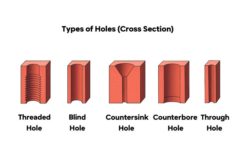
1. Through Hole
Definition: A hole that passes completely through a component from one side to the other.
Best Use: For bolts, pins, or wiring to fully pass through without interruption.
Applications: Structural brackets, mounting plates, PCB standoffs.
2. Blind Hole
Definition: A hole that does not pass through the entire part; it has a defined bottom depth.
Best Use: For threads, pins, or cavities where you don’t want to compromise the opposite face.
Applications: Gearbox housings, shafts, manifolds.
3. Counterbore Hole
Definition: A cylindrical flat-bottom recess over a hole to house fastener heads.
Best Use: To allow socket-head cap screws to sit flush or below the surface.
Applications: Machinery flanges, tool holders, steel mounting blocks.
4. Countersink Hole
Definition: A conical recess at a hole’s entrance for seating flat-head screws flush with the surface.
Best Use: For aesthetic or flush-mounted fasteners, especially in aerospace or enclosures.
Applications: Avionics panels, sheet metal enclosures, control knobs.
5. Tapped (Threaded) Hole
Definition: A hole with internal threads to accommodate bolts or machine screws.
Best Use: Fastening without needing access to the back side of a part.
Applications: Engine covers, chassis, electronic housings.
6. Spotface Hole
Definition: A shallow counterbore that provides a clean, flat seating surface for fasteners or washers.
Best Use: To ensure even clamping when mounting on uneven surfaces like castings.
Applications: Pumps, housings, injection-molded components.
7. Drilled Hole
Definition: A basic hole made by a rotating drill bit, typically rough before finishing.
Best Use: Initial stage for most precision holes that will later be reamed or tapped.
Applications: Universal—used across all sectors in almost every part.
8. Reamed Hole
Definition: A drilled hole finished to a precise diameter using a reamer for high-accuracy fits.
Best Use: Tighter tolerances and smooth finishes for press-fit or dowel locations.
Applications: Alignment pins, bearing bores, shaft supports.
9. Bored Hole
Definition: A hole refined or enlarged with a boring tool to achieve precise ID control on large diameters.
Best Use: When surface finish and tight tolerance are required for large holes beyond standard drills.
Applications: Cylinder bores, pump housings, pressure vessels.
10. Slot (Oblong Hole)
Definition: An elongated, rounded-end hole that allows movement or adjustability.
Best Use: Enables adjustable mounting or thermal expansion freedom in components.
Applications: Slotted rails, adjustable brackets, motor mounts.
11. Dowel Hole
Definition: A tightly toleranced hole for positioning pins used in precise alignments.
Best Use: To ensure parts align repeatably in jigs, fixtures, or assemblies.
Applications: Injection molds, CNC fixture plates, robotic tooling.
12. Tapped Blind Hole
Definition: A combination of a blind hole and internal threads; threads end before the hole bottom.
Best Use: For fasteners in closed-off areas where through holes aren’t possible or desired.
Applications: Electronics housings, sealed enclosures, medical equipment casings.
Summary Table
| Hole Type | Primary Function | Typical Application |
|---|---|---|
| Through Hole | Pass-through for fasteners or pins | Brackets, assemblies |
| Blind Hole | Stops at specific depth | Threaded bores, enclosed parts |
| Counterbore | Seats fastener head below surface | Machine plates |
| Countersink | Flush mount for flat-head screws | Enclosures, avionics |
| Tapped | Internal threads for screws | Frames, housing components |
| Spotface | Smooth surface for bolt seat | Uneven cast parts |
| Drilled | Initial rough cut | All industries |
| Reamed | Smooth precision fit | Dowel locations |
| Bored | Precise large diameter | Engine blocks |
| Slot | Allow movement/adjustment | Mounts, rails |
| Dowel | Fixed pin alignment | Fixtures, jigs |
| Tapped Blind | Sealed internal threads | Electronics, sealed devices |
Mastering these 12 hole types is essential for designing reliable and manufacturable components. Every hole should serve a purpose—whether for strength, alignment, or assembly. The more you understand their functions, the better your design will perform on the production floor and in the real world.
Engineering Drawing Callouts
Even the most brilliant design can fail without clear communication on the shop floor.
Engineering drawing callouts translate your design intent into machinist-ready information. Without precise callouts—especially for holes—you risk misinterpretation, incorrect toolpaths, rejected parts, and wasted time. Whether specifying diameter, depth, thread specs, or tolerances, clear hole callouts ensure your components are produced exactly as intended.

Key Components of a Hole Callout
| Callout Element | Meaning | Example |
|---|---|---|
| ⌀ Diameter | Specifies the width of the hole | ⌀10 mm |
| Depth | Indicates how deep the hole goes | Depth 15 mm |
| Thread Spec | Defines the thread pitch and size | M6x1.0-6H or ¼-20 UNC |
| Feature Type | Identifies countersink, counterbore, or spotface | ⌴ C’Bore ⌵ C’Sink |
| Quantity | Number of identical holes on the part | 4X ⌀5.0 |
| Position Tolerance | Controls allowable variation in hole placement | ⌀0.05 MMC True Position |
| Chamfer | Applies angle at hole entry to ease fastener fit | Chamfer 1.0 x 45° |
Callout Format Example
Here’s what a full hole callout might look like on a CAD drawing:
4X ⌀6.00 THRU
C’BORE ⌀10.00 x 3.0 DEEP
M6x1.0-6H, 12 mm DEEP
POS TOL ⌀0.05 MMC TO DATUMS A-B-C
This tells the machinist:
- There are 4 identical holes
- The base hole diameter is 6 mm, all the way through
- Each has a counterbore 10 mm wide, 3 mm deep
- Each hole is threaded M6x1.0, 12 mm deep
- Hole centers must fall within a true position tolerance of 0.05 mm at Maximum Material Condition, referenced from datum features A, B, and C
Standards to Reference
To ensure consistency and prevent ambiguity, hole callouts should follow recognized international standards. The most commonly used ones include:
- ASME Y14.5 (used in North America): Covers GD&T, thread specs, and positional tolerancing
- ISO 1101 (used internationally): Geometric tolerancing framework
- ISO 2768: General tolerance standards for holes without specific callouts
Tips for Effective Callouts
- Always include units (mm or in) to avoid confusion
- Group hole features by type for simplicity
- Use leader lines and clear spacing to improve legibility
- Specify thread class (e.g., 6H, 3B) for critical fits
- If surface finish is critical (e.g., for sealing), note it with Ra or roughness symbol
At Onlyindustries, we often help clients update or correct hole callouts before production begins. A misaligned thread depth or vague positional tolerance can delay entire assemblies—especially on multi-axis CNC projects or medical-grade parts.
Pro Tip: When unsure, add a detail view with section cuts showing hole geometry. It helps reduce back-and-forth with machinists and eliminates guesswork.
Bottom line? A well-documented hole saves you from costly surprises and rejected parts later on.
Hole Design Best Practices
Even a simple hole can cause complex problems if not designed correctly.
When it comes to CNC machining or precision fabrication, hole features directly affect manufacturability, durability, and part quality. Following best practices ensures strong assemblies, reduced lead times, and lower production costs. Whether you’re designing fastener holes, dowel holes, or press-fit cavities, small decisions in hole geometry can make a big difference on the shop floor.
Use Standard Hole Sizes
Always select hole diameters from standard drill series (letter, number, fractional, or metric). Avoid odd sizes that require custom tooling or interpolation. For instance, choosing a ⌀6.3 mm (standard metric) instead of ⌀6.25 mm could save reaming time and increase tool life.
Ensure Sufficient Wall Thickness
Maintain adequate material around holes—especially in corners, flanges, or thin-wall parts. A good rule of thumb is to keep the edge distance at least 1.5x the hole diameter to prevent cracking during torque or thermal stress.
Add Thread Reliefs for Tapped Holes
Threads should not terminate against the blind hole floor. Add a relief diameter or undercut at the bottom to ensure full thread engagement and allow the tap to exit cleanly. This avoids incomplete threads and broken taps.
Include Chamfers or Deburring Features
Chamfering the entry and exit of holes improves assembly fit, prevents thread damage, and makes insertion of fasteners smoother. Deburring is critical for safety, appearance, and part handling.
Use Positional Tolerances for Hole Patterns
When multiple holes must align (like on a gear plate or mounting bracket), define true position using GD&T with datum references. This is far more robust than relying on ±X/Y tolerances for each individual hole.
Sequence Finishing After Roughing
If your part includes reamed or bored holes, ensure they are machined after rough milling to preserve accuracy. Roughing can introduce stress or warp the part, shifting precision hole locations.
Avoid Deep, Narrow Blind Holes
Long blind holes are harder to tap, prone to chip buildup, and may require special tools. Limit thread depth to 1.5–2x the diameter unless strength testing proves otherwise. Use through-holes where possible for easier manufacturing and chip evacuation.
Group Hole Features Logically
On drawings, list holes by feature type—e.g., all through holes together, then all tapped holes, etc. This minimizes miscommunication and simplifies tool changes in CNC setups.
Recommended Design Parameters
| Design Element | Recommended Value | Why It Matters |
|---|---|---|
| Minimum Edge Distance | 1.5x hole diameter | Prevents stress cracks |
| Thread Engagement | 75% (1.5x diameter) | Balances strength and tool life |
| Chamfer Angle | 45° or 60° | Improves assembly & deburring |
| Max Blind Hole Depth | 3–4x diameter | Limits chip compaction & tool wear |
| Reamed Hole Pre-Drill | 0.2–0.4 mm undersized | Allows reamer to cut full profile |
Remember, the best hole designs don’t just fit—they also machine easily, assemble quickly, and perform reliably. Every radius, depth, and edge condition should be deliberate, not an afterthought.
Need help reviewing your hole geometry before sending it to production? At Onlyindustries, we offer DFM (Design for Manufacturability) feedback to help you avoid tolerance stack-up, thread issues, and costly redesigns—before the first chip is cut.
Conclusion
Thoughtfully designed holes are essential for part functionality, alignment, strength, and cost efficiency.
From through holes and tapped threads to precision bores and countersinks, every hole serves a specific role—and each requires attention to detail. Getting hole design right means faster production, fewer assembly issues, and better-performing products. It’s not just about geometry; it’s about purpose-driven engineering.
At Onlyindustries, we specialize in CNC machining with tight-tolerance hole features. Whether you’re designing surgical jigs, motor brackets, or aerospace housings, our team ensures your parts are built to spec—every hole, every time.
Need help optimizing your hole designs?
Reach out to Onlyindustries today for expert guidance and a fast-turn custom quote. Let’s make every hole count.