Skip to content
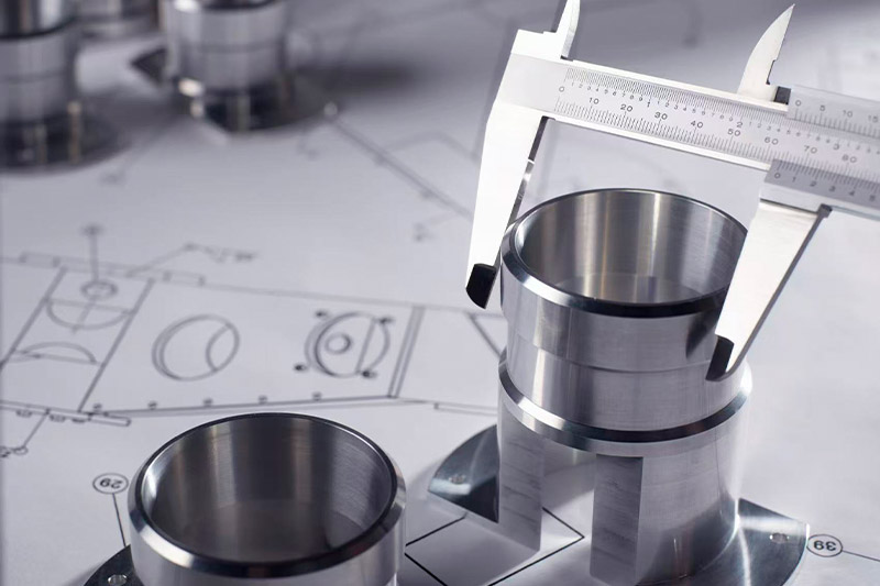
 In CNC machining, precision is everything—but not every feature needs micrometer-level tolerances. When dimensions don’t have specific callouts, ISO 2768 offers a reliable, global standard that ensures functionality without overcomplicating your drawings.
ISO 2768 defines general tolerances for linear, angular, and geometric features in the absence of explicitly stated tolerances. It’s essential for engineers and procurement specialists to understand how this standard impacts part design, cost, and manufacturability.
Let’s break down ISO 2768 and how it fits into your CNC workflow—whether you’re designing, quoting, or inspecting parts.
What Is ISO 2768?
Specifying tolerance for every feature on a drawing is overkill. That’s where ISO 2768 comes in.
ISO 2768 is an international standard for general tolerances that apply to machined parts when individual tolerances are not explicitly defined. It helps manufacturers interpret design intent without excessive annotation.
Two Parts of ISO 2768
- ISO 2768-1: Covers general linear and angular tolerances (length, thickness, radius, chamfers, angles)
- ISO 2768-2: Covers geometric tolerances (flatness, perpendicularity, symmetry, run-out)
It applies to metals and plastics alike—as long as tolerances aren’t otherwise specified. At Onlyindustries, we apply ISO 2768 intelligently to streamline part production while meeting critical tolerances when necessary.
Why ISO 2768 Is Important?
Here’s why ISO 2768 is so valuable in everyday design and manufacturing work:
Standardized Communication Between Designer & Manufacturer
ISO 2768 provides a universal language. By referencing a single line—like ISO 2768-mK—both design and machining teams instantly understand acceptable limits on dimensions and geometry.
This avoids long email threads and guessing games about how accurate “unspecified” dimensions should be. It ensures consistency, no matter the supplier’s location or local standards.
Prevents Over-Tolerancing—and Avoids Unnecessary Cost
Tight tolerances drive up cost. They increase machining time, tool wear, setup complexity, and inspection requirements. Many junior engineers default to ±0.01 mm even where ±0.2 mm would work just fine.
ISO 2768 stops this. It sets reasonable, achievable defaults for non-functional features, helping you focus tolerancing effort where it matters most—like bearing fits or sealing surfaces.
Simplifies Engineering Drawings
Rather than marking a tolerance on every single dimension, ISO 2768 lets you clear the clutter. Just one general note—General Tolerances: ISO 2768-mK—covers most of your drawing.
This makes drawings easier to read, interpret, and revise. Plus, it aligns with modern drafting tools like CAD/CAM systems that support general tolerancing structures.
Improves Manufacturability
ISO 2768 aligns with what CNC machines can already do—especially under class “m” (medium) or “K” (medium geometry). That means fewer rejects, smoother setup, and less post-machining cleanup.
When applied correctly, it enhances overall part manufacturability without sacrificing performance or function.
Enhances Inspection Efficiency
For quality teams, ISO 2768 reduces unnecessary measurement tasks. Inspectors can use calipers or CMMs based on the standard’s default tolerances—freeing them to focus on critical dimensions explicitly called out on the drawing.
This speeds up inspection cycles and reduces bottlenecks in production QA/QC processes.

As someone who’s worked on both sides—design and manufacturing—trust me, ISO 2768 isn’t just a standard. It’s a strategic tool that keeps engineering focused, costs in check, and teams aligned across the full product lifecycle.
ISO 2768-1: Linear and Angular Dimensions
Dimensional tolerancing without over-complication? That’s the promise of ISO 2768-1.
ISO 2768-1 is the foundation for general dimensional tolerances in mechanical design. It applies to linear dimensions, angular measurements, external radii, and chamfers—offering a clear system to specify default tolerances based on part size and required precision.
Instead of manually specifying tolerances for every feature, ISO 2768-1 allows me to define a tolerance class (f, m, c, or v) and let the standard handle the rest—cutting down on unnecessary detail while keeping designs functional and cost-effective.
Table 1.1: Linear Dimensions Tolerances (ISO 2768-1)
These tolerances apply to dimensions such as lengths, widths, and thicknesses, where no specific tolerance is stated. Values are in millimeters (mm).

Table 1.2: External Radii and Chamfer Heights
This table applies to round features like fillets, corners, and chamfers. It helps maintain clean transitions without demanding tight inspection controls on non-critical areas.
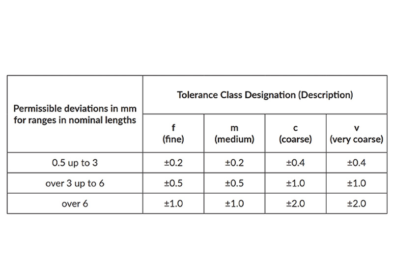
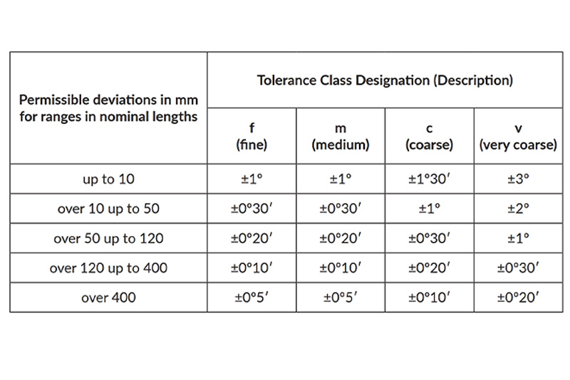
Table 1.3: Angular Dimensions
For tolerancing angles without detailed callouts, ISO 2768-1 offers a useful breakdown based on feature size and tolerance class.
ISO 2768-2: General Tolerances for Geometric Features
Geometry matters—but over-specifying form tolerances can waste time and money. ISO 2768-2 solves this by standardizing general geometric tolerances for features where function is not critical.
In my engineering practice, I’ve found ISO 2768-2 especially helpful for keeping shop drawings clean and manufacturers on the same page—without micromanaging features like flatness or run-out unless necessary.
These tolerances are classified into three levels: H (coarse), K (medium), and L (fine). ISO recommends using “K” for most CNC machined parts, unless the feature has specific form/function requirements.
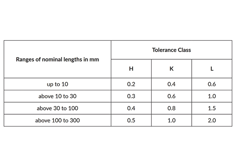
Table 2.1 – General Tolerances on Straightness and Flatness (ISO 2768-2)
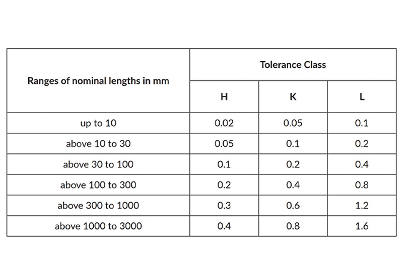
These values apply to straightness of edges and flatness of surfaces not explicitly toleranced.
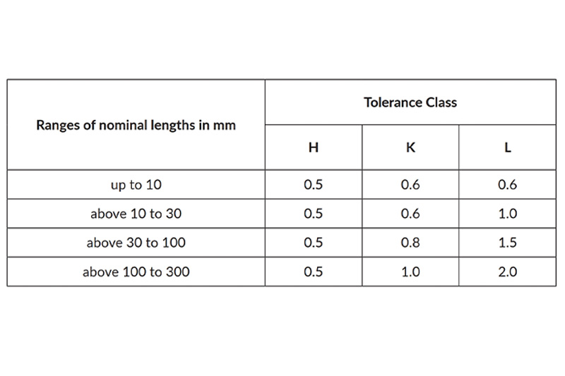
Table 2.2 – General Tolerances on Perpendicularity (ISO 2768-2)
Perpendicularity tolerances apply to faces or features where square alignment matters but isn’t critical. This is perfect for bracket holes, fixture blocks, and housings without tight assembly specs.
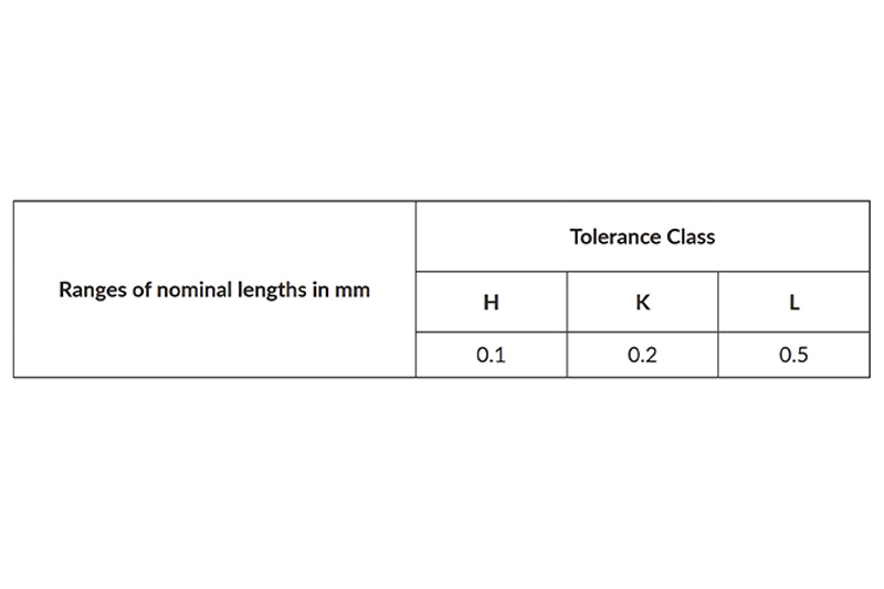
Table 2.3 – General Tolerances on Symmetry (ISO 2768-2)
Symmetry tolerances are particularly useful for designs where visual or weight balance matters but don’t affect critical fit or function. I’ve used them often in non-precision cover plates and enclosures.
Table 2.4 – General Tolerances on Circular Run-Out (ISO 2768-2)
Run-out tolerances are critical in rotating components like gears, wheels, or pulley hubs—where even minor deviation could introduce vibration. But again, if the feature isn’t mission-critical, using class K avoids over-control.
Frequently Asked Questions
Q1: Can ISO 2768 replace GD&T?
No. ISO 2768 fills in where tolerances are not specified. For critical features, explicit GD&T is still necessary.
Q2: Which tolerance class should I use?
- f – High-precision aerospace/medical parts
- m – Standard CNC machined components
- c/v – Rough cuts, weldments, large fabrications
Q3: Does ISO 2768 apply to plastic parts?
Yes, but plastics expand and warp more easily. Use wider tolerances and consider material-specific behaviors.
Q4: How do I indicate ISO 2768 on my drawing?
In the title block or general notes: “ISO 2768-mK” where “m” = medium linear and “K” = medium geometric tolerances.
Q5: What happens if I have both ISO 2768 and specific tolerances on the same drawing?
Explicit tolerances take priority over ISO 2768 default values.
Q6: Does ISO 2768 apply to threads or surface finishes?
No. These must be specified separately (e.g., ISO 965 for threads, Ra values for surface finish).
Conclusion
ISO 2768 is more than just a tolerance chart—it’s a tool that simplifies design, reduces costs, and increases communication clarity. By applying it correctly, you avoid over-engineering while maintaining functional quality across your CNC machined parts.
At Onlyindustries, we deliver micron-level tolerance control guided by ISO 2768 and other global standards—ensuring you get the quality you need without the hassle of unnecessary complexity.
Need guidance applying ISO 2768 to your parts or drawings? Contact our engineering team today for a review.