Skip to content
 In mechanical engineering and precision manufacturing, a fit defines the dimensional relationship between two mating parts—typically a shaft and a hole—when assembled. The correct fit choice impacts performance, reliability, assembly effort, and service life.
From sliding mechanisms to press-fit gears, knowing when to use clearance, transition, or interference fits ensures optimal function and cost efficiency.
What Is a Fit in Engineering?
In engineering, a fit describes the precise dimensional relationship between two mating components—usually a shaft and a hole—when assembled. This relationship determines whether the parts slide freely, align accurately, or lock tightly under load. Selecting the correct fit type is crucial because it influences the part’s operational performance, service life, and ease of assembly or disassembly.
A fit is defined by two main factors:
- Allowance – The intentional difference in size between the hole and the shaft. This determines whether there will be clearance (space), interference (tightness), or a balance of the two.
- Tolerance – The permissible variation in part dimensions that still allows the assembly to function as intended.
Engineering standards like ISO 286 and ANSI B4.1 classify fits into categories and provide precise dimensional ranges for each type. This standardization ensures compatibility and interchangeability between parts made by different manufacturers.
Why It Matters
The type of fit chosen directly impacts how parts interact in service:
- Performance: A sliding fit may be ideal for moving parts, while a press fit is better for transmitting torque.
- Durability: Correct fits minimize wear, prevent loosening under vibration, and reduce the risk of part failure.
- Manufacturing Cost: Tighter tolerances increase precision but also raise production costs; looser fits may be cheaper but reduce performance.
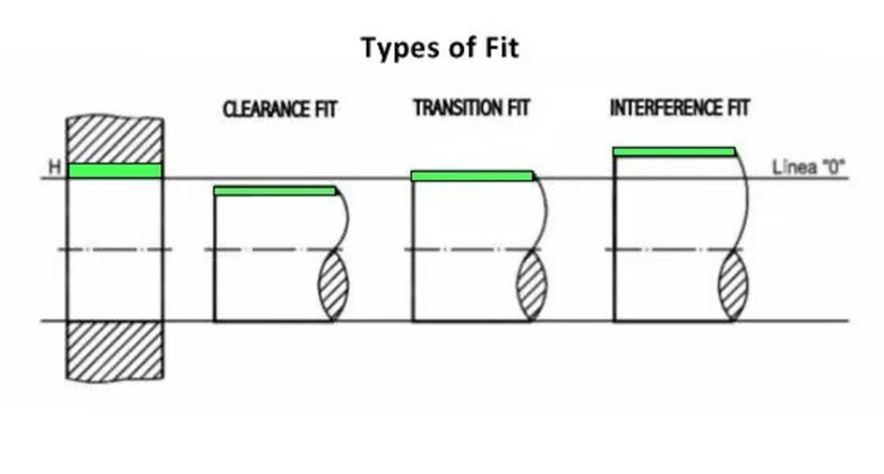
Common Categories of Fits
| Fit Type | Assembly Condition | Typical Use Case |
|---|---|---|
| Clearance Fit | Always space between parts | Sliding mechanisms, quick-change assemblies |
| Transition Fit | Small clearance or small interference | Accurate alignment with moderate holding power |
| Interference Fit | Always interference between parts | Permanent, high-strength joints |
Engineering Insight
When designing for fits, engineers must consider thermal expansion, material hardness, lubrication, and expected service conditions. For example, a shaft-hub assembly in an engine must handle temperature fluctuations without seizing, while still transmitting high torque—making fit selection a balance between precision and practicality.
Clearance Fit
A clearance fit is a type of engineering fit where there is always intentional space between the shaft (male part) and the hole (female part), ensuring they can move relative to each other without interference. This fit type is specifically designed for applications where ease of assembly, smooth movement, and quick disassembly are priorities.
Clearance fits are defined by a positive allowance, meaning the shaft’s maximum possible diameter is still smaller than the hole’s minimum possible diameter. This guarantees that the two parts will never bind together, even at the tightest tolerance limits.
When to Use a Clearance Fit
- When components must move freely without excessive friction.
- In assemblies requiring frequent removal or replacement.
- When operating conditions include thermal expansion but movement must be maintained.
Common Applications
- Sliding guides in machine tools
- Removable locating pins in jigs and fixtures
- Bushings and bearings for low-load, low-speed mechanisms
- Hinges or pivot joints that require free rotation
Subtypes of Clearance Fits
| Subtype | Description | Example Use |
|---|---|---|
| Loose Running Fit (RC9–RC10) | Large clearance for easy movement even under misalignment or contamination. | Conveyor rollers, rough guide rails |
| Close Running Fit (RC1–RC2) | Minimal clearance for precise guiding without binding. | Precision slides, instrument assemblies |
Advantages
- Very easy to assemble and disassemble without special tools.
- Low friction and reduced wear under proper lubrication.
- Tolerant to minor dimensional variations in manufacturing.
Limitations
- Lower load-carrying capacity compared to interference fits.
- Potential vibration or noise if clearance is too large.
- Less precise positioning under heavy or dynamic loads.
Engineering Insight
While clearance fits provide freedom of movement, excessive clearance can lead to instability and premature wear. Engineers must balance ease of assembly with functional stability by selecting the correct clearance class (ISO or ANSI) based on the application’s load, speed, and precision requirements.
Transition Fit
A transition fit is an engineering fit where the shaft and hole are dimensioned so that the resulting assembly may have either a small clearance or a slight interference, depending on the actual sizes produced within the specified tolerances. This makes it a “middle ground” between clearance and interference fits, balancing positional accuracy with moderate holding strength.
Unlike a clearance fit, a transition fit does not always guarantee free movement, and unlike a full interference fit, it does not always require significant force for assembly. This dual nature makes it ideal for applications that need precise location but not the full locking force of a press fit.
When to Use a Transition Fit
- When accurate positioning is required but disassembly should still be possible with moderate effort.
- In assemblies where load transmission is moderate rather than extreme.
- When part interchangeability and repeatable alignment are important.
Common Applications
- Gear hubs on shafts
- Couplings in rotating equipment
- Locating sleeves and bushings
- Machine tool components requiring precise location
Subtypes of Transition Fits
| Subtype | Description | Example Use |
|---|---|---|
| Locational Clearance Fit | Minimal clearance with precise location and slight movement possible. | Removable alignment pins |
| Locational Transition Fit | Balanced between clearance and interference for firm yet serviceable joints. | Gear hubs requiring accurate alignment and moderate holding |
Advantages
- Provides excellent positional accuracy compared to clearance fits.
- Moderate holding power without requiring extreme assembly force.
- Suitable for parts that need both precision and serviceability.
Limitations
- May require light pressing tools for assembly or removal.
- Not as secure under heavy torque or vibration as interference fits.
- Tighter manufacturing tolerances required than for clearance fits.
Engineering Insight
When specifying a transition fit, engineers must consider both functional requirements and manufacturing capabilities. Small variations in production can tip the fit toward clearance or interference. Using ISO 286 or ANSI B4.1 fit tables helps determine the correct tolerance combination (e.g., H7/k6 or H7/n6) to achieve the desired balance between accuracy and holding strength.
Interference Fit
An interference fit—also known as a press fit or shrink fit—is a type of engineering fit where the shaft is intentionally made larger than the hole it will be assembled into. This size difference creates a negative clearance, meaning that the parts cannot be joined without applying force, heat, or cooling. The interference generates high frictional forces that securely lock the parts together without the need for additional fasteners.
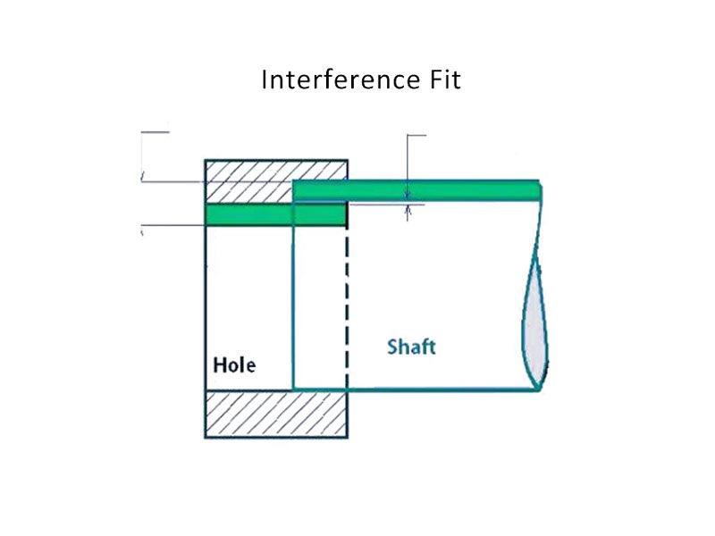
This fit type is widely used in applications where the joint must transmit high torque, endure heavy axial loads, and resist vibration over long service life. Once assembled, interference fits form strong, often permanent connections.
When to Use an Interference Fit
- When high torque transmission is required without slippage.
- For components that must remain permanently fixed during service.
- In high-load, high-vibration environments such as industrial machinery or rotating assemblies.
Common Applications
- Press-fit gears on drive shafts
- Bearings installed into housings
- Structural pins in heavy equipment
- Flywheels mounted on crankshafts
Subtypes of Interference Fits
| Subtype | Description | Example Use |
|---|---|---|
| Light Interference Fit | Minimal interference allowing assembly with moderate force or light heating/cooling. | Serviceable bearing mounts |
| Heavy Interference Fit | Significant interference for permanent, high-strength joints. | High-torque gear assemblies |
Advantages
- Maximum torque and load transmission capacity.
- Excellent resistance to loosening from vibration or shock.
- Eliminates the need for keys, splines, or additional fasteners.
Limitations
- Requires very tight machining tolerances to ensure proper fit.
- Disassembly can be difficult and may damage components.
- High assembly forces or thermal methods are necessary, increasing process complexity.
Engineering Insight
Designing an interference fit involves precise tolerance selection based on ISO 286 or ANSI B4.1 standards, considering material properties and expected operating conditions. Engineers often use thermal assembly methods—such as heating the female part to expand it or cooling the male part to shrink it—for easier installation. Surface finish (Ra 0.8–1.6 μm) is critical to reduce galling and ensure uniform contact pressure across the mating surfaces.
Fit Type Comparison
Understanding the differences between clearance, transition, and interference fits is critical for selecting the most suitable option for your engineering application. Each fit type balances assembly effort, holding strength, and precision in a unique way. The choice depends on how the parts will function together, the loads they will encounter, and the service requirements over their lifetime.
Detailed Fit Type Characteristics
| Fit Type | Clearance/Interference | Assembly Method | Holding Power | Common Applications |
|---|---|---|---|---|
| Clearance Fit | Always clearance (positive gap between parts) | Manual sliding or light push | Low | Sliding mechanisms, removable pins, bushings |
| Transition Fit | May be slight clearance or slight interference | Light pressing or tapping | Medium | Gear hubs, couplings, bearing seats |
| Interference Fit | Always interference (negative clearance) | Press fit, heating, or cooling required | High | Press-fit gears, structural pins, bearing races |
Key Insights for Engineers
- Clearance Fits excel where movement or quick disassembly is required, but they sacrifice holding strength.
- Transition Fits balance location accuracy with moderate holding ability, ideal for components that need precise alignment without extreme torque loads.
- Interference Fits provide maximum holding power and vibration resistance but require precise tolerances and controlled assembly methods.
Design Considerations
- Match fit type to functional requirements—don’t over-specify a tighter fit than necessary, as it may increase costs and complicate assembly.
- Consider thermal expansion—components operating at varying temperatures may loosen or tighten depending on fit choice.
- Factor in maintenance needs—clearance fits enable easy part replacement, whereas interference fits may require destructive removal.
Engineering Example
In an electric motor assembly, the rotor shaft is press-fitted into the bearing’s inner race (interference fit) to ensure zero slippage under torque. The bearing’s outer race uses a slip fit in the housing to allow for thermal expansion during operation without causing stress fractures or alignment issues.
Key Factors for Fit Selection
Choosing the correct fit type is not just about meeting dimensional requirements—it’s about ensuring the assembled parts function reliably throughout their service life. The right decision balances performance needs, manufacturability, and maintenance requirements. Overlooking any of these factors can lead to assembly failures, premature wear, or unnecessary production costs.
Critical Considerations for Engineers
- Functionality – Determine whether the parts need to move freely, locate accurately, or remain permanently fixed. For example, sliding guides require clearance fits, while gears under load benefit from interference fits.
- Load Transmission – If the joint must transfer torque, axial load, or resist vibration, opt for a tighter fit like a transition or interference fit.
- Material Properties – Softer materials may deform under high-pressure fits; materials with different thermal expansion rates require fits that can compensate for size changes under varying temperatures.
- Manufacturing Capability – High-precision fits demand strict tolerance control. Ensure your machining process can consistently achieve the required dimensional accuracy before specifying an interference fit.
- Assembly & Maintenance – Consider whether the part will be serviced or replaced. Clearance fits simplify disassembly, while interference fits may require special tools or destructive removal.
- Operating Conditions – Account for thermal cycling, lubrication, environmental exposure (corrosion, dust), and mechanical stresses that may affect fit performance over time.
Practical Decision Matrix
| Factor | Recommended Fit Type | Example Application |
|---|---|---|
| Frequent disassembly required | Clearance Fit | Fixture locating pins |
| High torque load | Interference Fit | Press-fit gear hubs |
| Accurate positioning, moderate load | Transition Fit | Bearing seats |
| Temperature variations expected | Clearance or Light Transition Fit | Machine shafts in heated environments |
Engineering Insight
When designing a gearbox, I once specified an interference fit for a shaft-to-gear connection without fully accounting for the aluminum housing’s thermal expansion. During operation, heat caused the assembly to over-tighten, leading to premature bearing wear. By adjusting to a transition fit, we maintained alignment while preventing excess stress—a lesson in balancing theory with practical operating conditions.
Manufacturing Guidelines
Even with the correct fit type selected, poor manufacturing practices can compromise assembly quality and part performance. Applying the right machining, inspection, and assembly methods ensures that the intended fit tolerances are achieved consistently in production. Each fit type—clearance, transition, and interference—has its own best practices to maximize durability, accuracy, and ease of assembly.
Clearance Fits – For Smooth Movement and Easy Disassembly
- Lubrication: Apply a thin layer of oil or grease during assembly to reduce wear and prevent corrosion over time.
- Clearance Control: Avoid excessive gap; too much clearance can cause misalignment or vibration in moving parts.
- Precision Locating Features: Use dowel pins, shoulders, or keyways to ensure accurate positioning even with clearance.
Transition Fits – Balancing Holding Strength and Serviceability
- Pre-Assembly Checks: Verify shaft and hole dimensions with calibrated micrometers or bore gauges before pressing.
- Assembly Tools: Use soft-faced hammers, hydraulic presses, or arbor presses to avoid damaging part surfaces.
- Chamfering: Add chamfers to both shaft and hole edges to guide insertion and prevent edge damage.
Interference Fits – Maximum Strength and Vibration Resistance
- Thermal Assembly Methods: Heat the female part (e.g., using an induction heater) or chill the male part (dry ice, liquid nitrogen) to ease insertion and reduce press force requirements.
- Surface Finish Control: Aim for Ra 0.8–1.6 μm to ensure smooth assembly without scoring or galling.
- Stress Considerations: Avoid applying interference fits to thin-walled components without proper stress analysis—excessive hoop stress can cause cracks or distortion.
Recommended Inspection & Quality Control
| Fit Type | Critical Measurement | Inspection Tool |
|---|---|---|
| Clearance | Shaft OD, Hole ID | Micrometer, Bore Gauge |
| Transition | Shaft/Hole Size Difference | Micrometer + Coordinate Measuring Machine (CMM) |
| Interference | Negative Clearance & Roundness | Precision Bore Gauge, Roundness Tester |
Engineering Insight
In one production run of hydraulic pump shafts, we initially skipped thermal assembly for interference fits, relying solely on press force. This caused micro-scoring and reduced shaft life. Switching to a heat-and-chill method eliminated damage and sped up assembly—proving that fit selection is only half the story; proper manufacturing technique is just as critical.
Conclusion
In precision engineering, selecting the right fit type is as important as the part design itself. Clearance, transition, and interference fits each offer distinct advantages, and understanding their behavior under load, temperature change, and operational stress ensures your assemblies perform as intended. The right choice balances strength, serviceability, and manufacturing practicality.
Clearance fits excel in applications requiring easy movement and quick disassembly, such as guide rails or removable pins. Transition fits strike a balance—providing accurate positioning with moderate holding strength, ideal for couplings or gear hubs. Interference fits deliver maximum torque resistance and vibration stability, making them the go-to choice for permanent, high-load assemblies like bearing races or press-fit gears.
Key Takeaways
- Match the fit to the function: Don’t over-engineer a permanent fit where maintenance access is needed, or under-spec a clearance fit for a torque-transmitting joint.
- Consider manufacturing capability: Even the perfect fit on paper fails if production can’t hold the required tolerances consistently.
- Plan for assembly conditions: Account for temperature, lubrication, and available tools when determining your fit approach.
- Verify through measurement: Use precision inspection to confirm dimensions before assembly—especially for interference and transition fits.
Professional Insight
In my experience working on aerospace landing gear components, a well-chosen fit type can save thousands in rework and downtime. On one project, switching from a tight transition fit to a light interference fit improved torque retention by 25% without compromising serviceability—proving that small tolerance changes can have big operational impacts.
Ultimately, fit selection isn’t just about dimensions; it’s about engineering foresight. The right choice ensures that your components assemble smoothly, perform reliably, and meet their intended service life with minimal maintenance.ance control for all fit types, with ISO-compliant inspections to guarantee that your parts perform exactly as intended.