Skip to content
 In precision engineering, fit types determine how mating components assemble, function, and perform under load. Two of the most common are press fits and slip fits, each offering unique characteristics that impact assembly methods, tolerances, service life, and maintenance.
Whether in CNC machining, automotive, aerospace, robotics, or industrial equipment, choosing the right fit type is essential to meet your performance goals.
What Is a Press Fit?
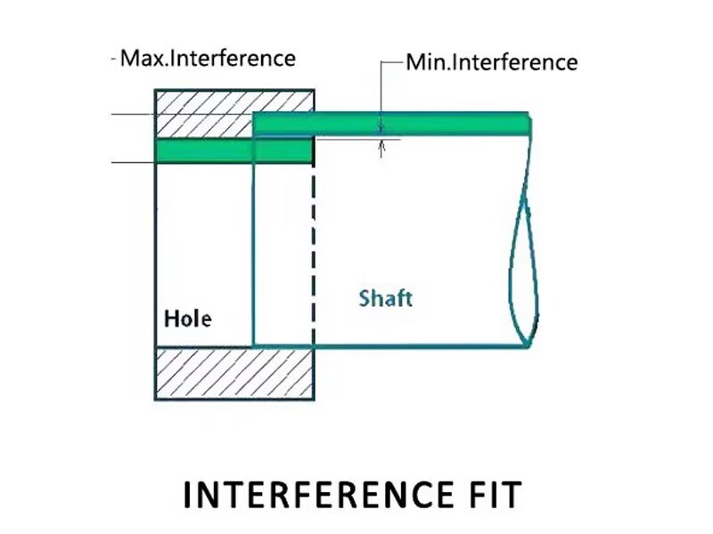
A press fit, also called an interference fit, is a fastening method where the male component (such as a shaft) is intentionally made slightly larger than the female component (such as a hole) to create a tight, force-based connection. This size difference—known as the interference—generates significant friction when the parts are joined, eliminating the need for additional fasteners like screws or adhesives.
The core principle of a press fit is to create enough contact pressure between the mating surfaces so that they can withstand operational loads, torque, and vibrations without slipping or loosening. The assembly process can involve mechanical force, heat expansion of the female part, cooling of the male part, or a combination of these to ease insertion while still achieving a secure fit once the parts reach the same temperature.
Key Characteristics
- Interference-based connection: The shaft diameter is larger than the hole diameter by a controlled amount.
- Friction locking: The joint strength comes from high friction between the surfaces.
- Permanent or semi-permanent: Press fits are typically not intended for frequent disassembly.
Assembly Methods
- Mechanical pressing: Using a hydraulic or arbor press to push the parts together.
- Thermal fitting: Heating the female part to expand it, or cooling the male part to shrink it, before assembly.
- Combination approach: Using both temperature change and press force for easier assembly of tight-tolerance fits.
Typical Applications
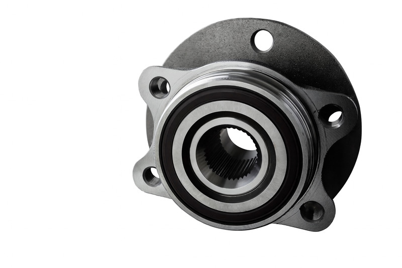
- Pressing bearings into housings for automotive, aerospace, and industrial machinery.
- Mounting gears onto shafts in transmission systems.
- Securing bushings in precision equipment.
- Attaching hubs or pulleys to drive shafts.
Advantages
- High torque and load capacity due to large friction area.
- Resistance to loosening under vibration or dynamic forces.
- Eliminates the need for adhesives, pins, or keyways in many designs.
Limitations
- Requires precise manufacturing tolerances to avoid assembly failure or part damage.
- Can cause deformation or stress in thin-walled parts.
- Disassembly can be difficult and often damages one or both parts.
Engineering Tip
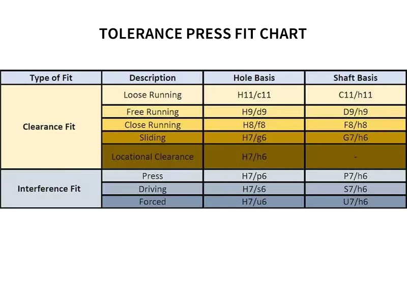
When designing for a press fit, follow ISO 286 or ANSI B4.1 fit tolerance standards. Also, ensure proper surface finish (Ra 0.8–1.6 μm) and concentricity for optimal performance. Using a small chamfer on both parts can guide the fit and reduce edge damage during assembly.
What Is a Slip Fit?
A slip fit, also known as a clearance fit, is a method of assembling two parts where the male component (such as a shaft) is slightly smaller than the female component (such as a hole). This dimensional difference creates a small amount of clearance, allowing the male part to slide into place with minimal or no force. Unlike press fits, slip fits rely on the ease of movement rather than interference to hold components together.
The clearance in a slip fit is carefully controlled to ensure proper positioning while still allowing for assembly, disassembly, and thermal expansion during operation. This type of fit is ideal for applications where frequent maintenance, part replacement, or positional adjustment is required without damaging the components.
Key Characteristics
- Clearance-based connection: The hole diameter is intentionally larger than the shaft diameter by a small amount.
- Ease of assembly: Components can be joined manually or with light pushing, without presses or thermal assistance.
- Serviceability: Designed for easy removal and replacement of components.
Assembly Methods
- Manual insertion: Parts are slid into place by hand or with minimal mechanical assistance.
- Light push fit: Slight friction may be present, but no significant force is required.
- Lubricated fit: Applying a thin film of lubricant to ensure smooth movement and prevent wear during installation.
Typical Applications
- Locating pins in jigs and fixtures for CNC machining.
- Removable shafts in motors, gearboxes, or couplings.
- Guide bushings for machine tools.
- Alignment sleeves in precision assemblies.
Advantages
- Fast, easy assembly without special tools or heating/cooling.
- Lower manufacturing and assembly costs compared to interference fits.
- Allows for thermal expansion and contraction without binding.
- Facilitates frequent maintenance and part replacement.
Limitations
- Lower load and torque capacity compared to press fits.
- Potential for slight movement or play under dynamic loads.
- May require secondary locking features in high-vibration environments.
Engineering Tip
When designing for slip fits, follow tolerance guidelines from ISO 286 or ANSI B4.1 to ensure proper clearance. Maintain consistent surface finish and roundness to prevent misalignment. For high-precision applications, incorporate additional locating features such as shoulders, dowel pins, or alignment keys.
Press Fit vs. Slip Fit: Side-by-Side Comparison
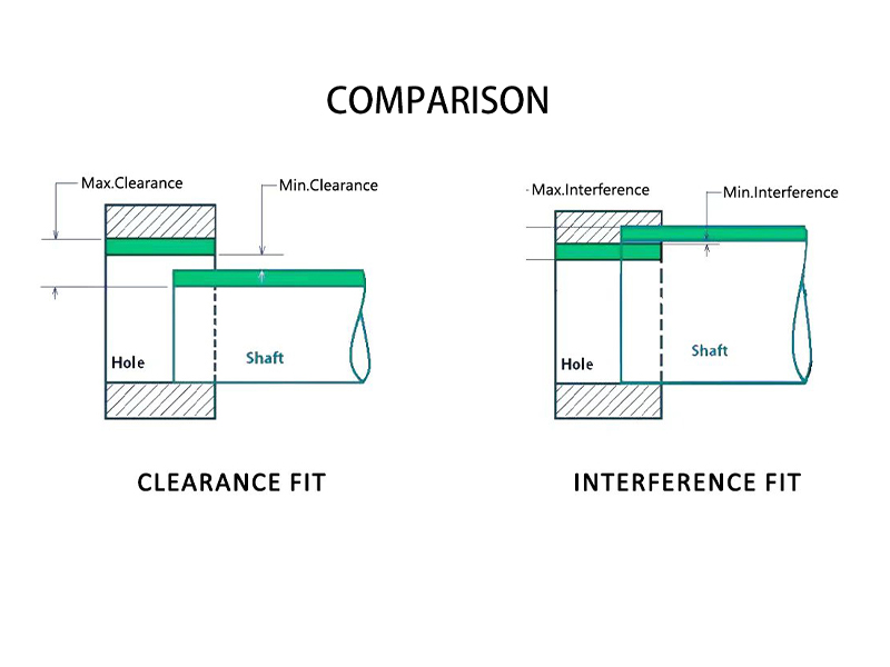
In manufacturing, the choice between a press fit and a slip fit directly impacts assembly methods, mechanical performance, and maintenance requirements. While both involve mating a shaft with a hole, the key difference lies in whether the fit is based on interference or clearance. Below is a detailed, side-by-side breakdown of their characteristics, advantages, and limitations.
Comparison Table
| Feature | Press Fit (Interference Fit) | Slip Fit (Clearance Fit) |
|---|---|---|
| Fit Type | Interference — shaft diameter is slightly larger than hole | Clearance — shaft diameter is slightly smaller than hole |
| Assembly Method | Requires press force, heating, or cooling for insertion | Manual or light push assembly, often without tools |
| Holding Mechanism | Friction and elastic deformation from interference | Gravity, light friction, or secondary locking features |
| Strength & Torque Capacity | High — suitable for torque-transmitting, load-bearing applications | Low to medium — not ideal for high-torque loads |
| Disassembly | Difficult — may require force or cause part damage | Easy — parts can be removed without special tools |
| Common Applications | Bearings in housings, gears on shafts, bushings, pulleys | Locating pins, removable shafts, guide bushings |
| Precision Requirement | Very high — tolerances within microns | Moderate — allows more leniency in manufacturing |
| Thermal Expansion Impact | May tighten fit with heat, potentially increasing stress | Allows for movement and expansion without binding |
| Example Tolerances* | Shaft Ø 10.02 mm / Hole Ø 10.00 mm (negative clearance) | Shaft Ø 9.98 mm / Hole Ø 10.00 mm (positive clearance) |
*Exact tolerances should follow ISO 286 or ANSI fit standards.
Key Takeaways
- Use press fits when you need permanent, vibration-resistant joints capable of handling high loads and torque.
- Use slip fits when you require easy assembly, disassembly, or positional adjustment during operation.
- Surface finish, roundness, and cylindricity are critical in both fit types to ensure proper function and longevity.
Engineering Insight
When deciding between press and slip fits, evaluate not just load requirements but also maintenance frequency, environmental conditions, and assembly capabilities. In many precision assemblies, designers combine both — for example, a press fit for torque transfer and a slip fit for alignment features.
Tolerances in Press and Slip Fits
In precision manufacturing, tolerances define the allowable variation in part dimensions to achieve the desired fit between mating components. For press fits and slip fits, the difference between shaft and hole sizes determines whether the assembly will rely on interference (tight fit) or clearance (loose fit). Achieving the correct tolerance is critical for performance, assembly ease, and service life.
Understanding Tolerance Ranges
- Press Fit (Interference Fit): The shaft diameter is slightly larger than the hole, resulting in negative clearance. This ensures a tight, friction-locked connection that often requires force, heating, or cooling during assembly.
- Slip Fit (Clearance Fit): The shaft diameter is slightly smaller than the hole, providing positive clearance for smooth insertion and removal without excessive force.
Example Tolerance Values*
| Fit Type | Example Shaft Diameter | Example Hole Diameter | Clearance/Interference |
|---|---|---|---|
| Press Fit | Ø 10.02 mm | Ø 10.00 mm | -0.02 mm (interference) |
| Slip Fit | Ø 9.98 mm | Ø 10.00 mm | +0.02 mm (clearance) |
*These values are illustrative — actual tolerances should comply with ISO 286 or ANSI fit standards for specific applications.
Factors Affecting Tolerance Selection
- Material Properties: Softer metals may deform slightly, requiring adjusted interference or clearance values.
- Operating Temperature: Thermal expansion can increase or decrease fit tightness, so allowances must be made for the working environment.
- Surface Finish: Rougher surfaces reduce effective clearance or interference and may increase wear during assembly.
- Roundness & Cylindricity: Deviations from perfect geometry can lead to inconsistent fits, even if nominal dimensions are correct.
Inspection & Quality Control
Precision measuring tools like micrometers, bore gauges, and Coordinate Measuring Machines (CMM) are essential for verifying shaft and hole sizes. For critical assemblies, fit verification is performed before final installation to avoid costly rework.
Engineering Insight
Overly tight press fits risk damaging thin-walled parts or creating excessive residual stress, while overly loose slip fits may lead to misalignment or vibration. The optimal tolerance balances assembly ease with operational reliability — a decision best made in collaboration between design and manufacturing engineers. tools.
Choosing the Right Fit
Selecting between a press fit and a slip fit is a decision that directly impacts assembly efficiency, long-term performance, and maintenance requirements. The choice should be based on the functional demands of the application, the operational environment, and the manufacturing capabilities available.
Key Decision Factors
- Joint Permanence:
- Press Fit: Best for permanent assemblies where the components are not intended to be separated during their service life, such as bearings in motor housings.
- Slip Fit: Suitable for assemblies that require periodic disassembly, such as shafts in maintenance-heavy machinery.
- Load and Torque Requirements:
- Press Fit: Offers high torque capacity and resists axial loads due to the friction from interference.
- Slip Fit: Better for low-load or non-torque-transmitting connections.
- Maintenance Frequency:
- Press Fit: Difficult to disassemble without special tools or heating, making it less suited for parts requiring frequent servicing.
- Slip Fit: Easy to assemble and remove, reducing downtime for repairs or replacements.
- Thermal Expansion Considerations:
- Press Fit: May become tighter at operating temperature, which can risk over-stressing thin components.
- Slip Fit: Accommodates expansion and contraction without binding.
- Manufacturing Capability:
- Press fits require high-precision machining and strict tolerance control.
- Slip fits can be more forgiving, allowing for slightly broader tolerance ranges.
Application Scenarios
| Scenario | Recommended Fit | Reason |
|---|---|---|
| High-speed gearbox bearing installation | Press Fit | Prevents bearing movement under torque and vibration |
| Locating pins in a welding fixture | Slip Fit | Allows quick changeover and positional accuracy |
| Engine crankshaft gear mounting | Press Fit | Ensures secure torque transfer and timing stability |
| Removable coupling in maintenance assembly | Slip Fit | Facilitates easy disassembly and replacement |
Engineering Insight
While functional requirements often dictate fit type, the decision should also consider long-term serviceability, manufacturing cost, and risk of part damage during assembly or removal. A well-chosen fit ensures the perfect balance between strength, ease of maintenance, and dimensional integrity throughout the product’s lifecycle.
Practical Manufacturing Tips
Applying best practices during manufacturing and assembly is essential for ensuring both press fits and slip fits perform as intended. By controlling machining quality, surface preparation, and assembly techniques, you can improve consistency, reduce wear, and extend component life.
Best Practices for Press Fits
- Guide Features: Add a 15°–30° chamfer on both male and female parts to guide insertion smoothly and prevent edge damage during pressing.
- Thermal Assistance:
- Heat the female part (e.g., to 150–200°C for steel) to expand the bore diameter before assembly.
- Chill the male part (e.g., using dry ice or liquid nitrogen) to shrink its diameter temporarily for easier insertion.
- Surface Finish Control: Maintain a surface roughness of Ra 0.8–1.6 μm to ensure optimal friction without causing scoring or galling.
- Assembly Equipment: Use an arbor press or hydraulic press to apply steady, uniform force; avoid hammering to prevent misalignment and damage.
- Tolerance Verification: Confirm actual diameters using micrometers or bore gauges to ensure the designed interference is achieved.
Best Practices for Slip Fits
- Lubrication: Apply a light coat of assembly oil or grease to minimize friction and prevent galling during insertion or removal.
- Consistent Clearance: Maintain uniform radial clearance (typically 0.01–0.05 mm for precision fits) to avoid binding and ensure accurate alignment.
- Precision Locating Features: Incorporate dowel pins, shoulders, or keyways to maintain positioning accuracy while still allowing disassembly.
- Chamfers & Lead-Ins: Use small chamfers or radii to help guide the mating parts together and prevent damage to edges.
- Protection Against Contaminants: Use dust caps, seals, or covers in environments prone to dirt or debris to prevent clearance interference over time.
Inspection & Quality Control
| Fit Type | Critical Checks | Recommended Tools |
|---|---|---|
| Press Fit | Interference value, concentricity, surface finish | Micrometer, dial bore gauge, profilometer |
| Slip Fit | Radial clearance, roundness, positional accuracy | Plug gauge, coordinate measuring machine (CMM) |
Engineering Insight
Even with perfect design tolerances, improper assembly technique can compromise fit quality. By combining precise machining with controlled environmental conditions during assembly, you can minimize stress on components and achieve consistent, high-performance fits that meet both functional and longevity goals.
Conclusion
Both press fits and slip fits play crucial roles in mechanical design and manufacturing, but their success depends on selecting the right fit for the application and executing it with precision. While press fits deliver exceptional strength and permanence through interference, slip fits excel in serviceability, ease of assembly, and tolerance for thermal movement.
In my experience, overlooking small details—like surface finish quality, proper chamfering, or exact clearance control—can turn an otherwise sound design into a maintenance problem. A well-executed press fit can operate flawlessly for decades, while a properly designed slip fit can enable fast, repeatable disassembly without wear or misalignment.
Ultimately, the choice comes down to answering a few key questions:
- Will the joint be permanent or require regular servicing?
- Is the primary need torque transmission or positional accuracy?
- Can your production process hold the required tolerances consistently?
By addressing these factors early in the design phase, you not only improve performance but also reduce long-term costs and downtime. Whether it’s a high-torque press fit for a gearbox or a precision slip fit for a removable spindle, aligning the fit type with your application’s demands ensures optimal reliability and efficiency.
In short: Press fits for permanence and strength, slip fits for flexibility and serviceability. Match the method to the mission, and your assemblies will thank you over their service life.