Skip to content
 Transmission shafts are indispensable components in mechanical systems, forming the backbone of torque transfer across various industries—from automotive drivetrains to aerospace rotors and industrial gearboxes. Whether you’re an engineer designing drivetrain assemblies or a procurement manager sourcing custom shafts, understanding how these components are specified, manufactured, and applied is crucial.
This guide provides a complete overview of transmission shafts: types, materials, design fundamentals, and modern manufacturing practices.
What Is a Transmission Shaft?
Power without direction is wasted—and that’s exactly the problem transmission shafts are engineered to solve. Without these components, rotational energy would go nowhere useful.
A transmission shaft is a mechanical component that transmits torque and rotation between two points within a machine or system. It ensures seamless mechanical connection between power sources and output devices, allowing for reliable and efficient motion transfer in diverse applications.
So why should we pay close attention to something that seems so simple? Because it’s not. Transmission shafts often operate under complex loads—combining torque, bending, axial stress, and rotational speeds. Understanding how they work—and how they fail—is essential for robust mechanical design.
What Makes a Shaft Different from Just a Rod?
A rod may only resist axial loads or act as a support. A transmission shaft, on the other hand, is built to transmit power—and that distinction drives everything from its material choice to its surface finish. Shafts are typically made to rotate and endure dynamic loading, often while supporting other components like gears, sprockets, and pulleys.
Core Mechanical Functions
- Torque Transmission: The shaft carries rotational force from one point to another, such as from a motor to a gearbox.
- Support for Rotating Components: It acts as a structural platform for parts like flywheels, pulleys, and timing gears.
- Vibration and Deflection Control: The shaft maintains system balance and integrity even during fluctuating loads.
Real-World Example: Automotive Drive Shaft
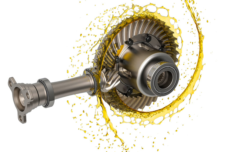
In a car, the transmission shaft connects the transmission to the differential. While accelerating, it not only spins under high torque but also has to cope with road-induced vibration and dynamic misalignment. In high-performance vehicles, the material and balance of this shaft can influence everything from fuel efficiency to ride quality.
Types of Loads on a Transmission Shaft
| Load Type | Description | Impact on Design |
|---|---|---|
| Torque | Rotational force applied to the shaft | Determines diameter and material strength |
| Axial Load | Force along the axis of rotation | Requires additional structural support |
| Bending Load | Weight from gears or pulleys mounted on the shaft | Influences shaft length and deflection limits |
| Shear Load | Force trying to cut across the shaft’s diameter | Important for spline/keyway design |
Why It Matters in Design
Even slight miscalculations in shaft design can lead to vibration, noise, premature bearing wear, or even catastrophic failure. For example, a shaft that’s too slender will bend under load, misalign gears, and cause transmission errors. On the flip side, overdesigning adds unnecessary weight and cost.
Common Shaft Standards
- DIN 748: For standard shaft dimensions and tolerances
- ISO 286: Fit system for shaft and hole assemblies
- AGMA/ANSI: For shaft design in gear systems
My Experience with Custom Shaft Projects
One of our recent projects involved a CNC-machined spindle shaft for a customer in the robotics industry. The challenge was to balance high rotational accuracy (≤ 10 microns) with load-bearing capacity in a lightweight frame. Using 7075 aluminum with precise surface grinding, we met all performance benchmarks—and reduced their weight by 30%.
Conclusion
To sum up, a transmission shaft is far more than just a rotating rod. It’s a mechanical lifeline that connects and supports multiple moving parts, often under high stress and demanding environments. Getting it right means understanding the loads it bears, the precision it requires, and the role it plays in the broader mechanical system.
Types of Transmission Shafts
Choosing the wrong type of shaft can lead to misalignment, vibration, or even catastrophic failure. Knowing the right type ensures the system works flawlessly.
Transmission shafts come in several types based on their role in a powertrain. Each is engineered to fulfill specific tasks—ranging from direct power delivery to precision spindle rotation.
If you’re designing or sourcing a shaft, selecting the correct type isn’t optional—it’s foundational. Let’s break down the six most common types of transmission shafts and where they fit into modern mechanical systems.
What Are the Main Types of Transmission Shafts?
Transmission shafts are broadly categorized by their function and installation environment. Here’s a structured overview:
| Type | Description | Typical Applications |
|---|---|---|
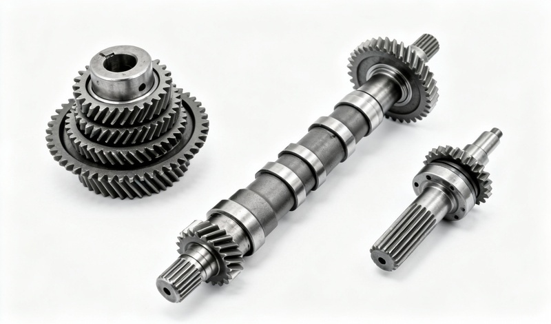
| Main Shaft | The primary rotating component in a powertrain that directly delivers mechanical power. | Gearboxes, motors, generators |
| Counter Shaft | A secondary shaft placed parallel to the main shaft that receives motion and redistributes it through gearsets. | Manual transmissions, lathe gearboxes |
| Line Shaft | A long shaft that connects multiple machines or tools, often supported by bearings along its length. | Textile mills, power plants, conveyor systems |
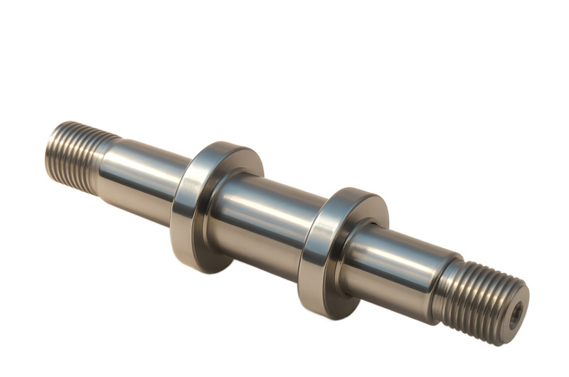
| Spindle Shaft | A precision shaft designed for rotational accuracy in tools or workpieces. | CNC machining centers, drilling rigs |
| Drive Shaft | Transmits torque from the engine or motor to other mechanical components—typically over longer distances. | Cars, trucks, marine drives |
| Jack Shaft | An intermediate shaft used to connect misaligned drive and driven components. | Motorcycles, snowmobiles, custom automation |
Main Shaft vs. Counter Shaft
The main shaft carries output power and is typically subject to higher loads. In contrast, the counter shaft is more about redistributing torque and enabling gear shifts. In automotive gearboxes, they work in tandem—one spinning at engine speed and the other adapting speed or torque via gear engagement.
Spindle Shaft Use Case: High-Speed CNC
In a CNC machine I helped develop, we used a spindle shaft that needed sub-10 micron radial runout. This required heat-treated 4340 alloy steel and cylindrical grinding. The accuracy was essential to avoid vibration and maintain cutting precision at 12,000 RPM.
When to Use a Jack Shaft
Jack shafts are lifesavers when your driving and driven components don’t align. They’re frequently used in custom builds where layout constraints prevent direct coupling. They also help change speed ratios by integrating pulley systems on either end.
Selection Tips
- Length Constraints: Choose a line shaft for long-distance transmission; avoid main shafts in unsupported spans.
- Speed & Precision: Use spindle shafts where low runout and high RPM are required.
- Misalignment: Go with a jack shaft to resolve installation geometry challenges.
Conclusion
Each transmission shaft type serves a unique function in a mechanical system. Whether you’re handling high torque, long distances, or tight tolerances, selecting the right shaft type ensures system integrity, performance, and longevity. Don’t generalize—engineer the specific solution your application needs.
Common Materials for Transmission Shafts
Poor material choice can doom a transmission shaft before it even rotates—leading to early wear, fatigue cracks, or catastrophic failure under load.
The right material for a transmission shaft balances strength, machinability, fatigue resistance, and cost. Choices vary depending on whether you need corrosion resistance, high torque capacity, or lightweight performance.
Let’s break down the most commonly used shaft materials, their advantages, and which applications they best suit—so you can avoid trial-and-error in your next project.
What Are the Best Materials for Transmission Shafts?
The material you choose directly impacts shaft performance, life cycle, and manufacturing complexity. Here’s a comparative overview of key shaft materials:
| Material | Key Benefits | Ideal Uses |
|---|---|---|
| C45 / 1045 Carbon Steel | Affordable, good tensile strength, easy to machine and weld | General-purpose shafts in machinery and light vehicles |
| 4140 / 4340 Alloy Steel | High tensile strength, fatigue resistance, heat treatable | High-load applications in automotive, aerospace, mining |
| SS304 / SS316 Stainless Steel | Corrosion resistance, smooth finish, food/medical safety | Marine systems, food-grade machines, medical robotics |
| 6061 / 7075 Aluminum | Lightweight, corrosion-resistant, easily machined | Robotics, UAVs, electric vehicles, aircraft controls |
| Ti-6Al-4V Titanium | Best strength-to-weight ratio, corrosion resistance | Motorsport, defense, aerospace actuators |
When to Use Carbon vs Alloy Steel
Carbon steel (like C45) is perfect for moderate loads, but once you’re dealing with cyclical torque, vibrations, or impact loading, step up to an alloy like 4140 or 4340. In one recent project, we replaced a cracked C45 shaft with induction-hardened 4340 and saw a 3X service life increase under the same conditions.
Aluminum for Weight-Sensitive Designs
In lightweight designs like drones or robotic arms, aluminum (especially 7075) is a game-changer. It’s easy to machine, resists corrosion, and dramatically reduces rotational inertia. I once helped a startup cut system weight by 40% by switching from mild steel shafts to 7075-T6 aluminum with anodizing.
Corrosion Resistance Matters
If you’re designing for humid, saline, or chemical environments—think food factories or marine gear—stainless steel or titanium is a must. SS316, for example, can withstand saltwater without corroding, and it’s often used for rudder shafts or offshore pump drives.
Heat Treatment Considerations
- 4140 / 4340 Alloy: Can be quenched and tempered to achieve 1000+ MPa tensile strength.
- Carbon Steel: Easier to weld and cut but usually needs surface hardening for wear resistance.
- Titanium: Excellent in raw form; no heat treatment usually required.
Cost vs Performance
| Material | Relative Cost | Machinability | Durability |
|---|---|---|---|
| Carbon Steel | Low | High | Moderate |
| Alloy Steel | Medium | Moderate | High |
| Stainless Steel | High | Low | Medium |
| Aluminum | Medium | High | Low to Medium |
| Titanium | Very High | Low | Very High |
Choosing materials involves trade-offs. Here’s a quick perspective:
Conclusion
There’s no one-size-fits-all material for transmission shafts. What works for a conveyor line might fail in an aerospace actuator. Your selection should match mechanical demands, environmental exposure, and cost targets. With the right material, your shaft won’t just rotate—it’ll perform reliably for years.nd fatigue-prone applications, use quenched and tempered alloy steels like 4340.
Key Design Considerations
Designing a transmission shaft isn’t just about selecting a material and diameter—overlooking stress points or misalignment risks can lead to costly failures.
Effective transmission shaft design ensures durability, balance, and load transfer efficiency. To get it right, you need to consider mechanical stresses, geometric features, fit tolerances, and finish quality—all tailored to real-world operating conditions.
Let me walk you through the most critical design elements that determine shaft performance in high-speed, high-load, and precision environments.
What Are the Most Important Shaft Design Factors?
There are five foundational aspects every engineer should assess when designing a transmission shaft for mechanical applications:
1. Load Calculations
Loads dictate shaft dimensions, material selection, and structural features. The main types of loads include:
- Torsional Load (Torque): Determines the required diameter and torsional strength.
- Bending Load: Arises from overhung gears, pulleys, or unsupported shaft spans.
- Axial Load: Results from thrust bearings or helical gears pushing along the shaft axis.
Formula Example:
Torque (T) = (π × τ × d³) / 16
Where τ = shear stress, d = shaft diameter
2. Shaft Dimensions
The balance between shaft diameter and length determines resistance to deflection and vibration. Longer shafts require larger diameters or support bearings to control deflection.
| Design Goal | Recommendation |
|---|---|
| Minimize deflection | Use short spans or add supports |
| Increase torque capacity | Increase shaft diameter |
| Prevent resonance | Adjust natural frequency with mass/stiffness |
3. Surface Finish
A shaft’s surface finish impacts wear rate and fatigue life. Rough surfaces become initiation points for microcracks. Common finishing operations include:
- Grinding: For precision diameter control and smooth Ra ≤ 0.8 μm
- Polishing: Reduces micro-abrasions in dynamic assemblies
- Plating/Coating: Adds corrosion and wear resistance (e.g., chrome, phosphate)
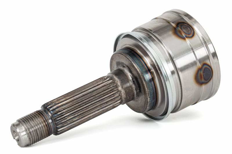
4. Keyways, Splines & Threads
Coupling features like keyways and splines are necessary for torque transfer—but they introduce stress concentrations. To minimize failure risk:
- Use rounded keyway corners or relief grooves
- Keep spline profiles within recommended stress limits
- Avoid sharp internal threads near high-load regions
In one shaft failure analysis I supported, a keyway machined too deep reduced cross-sectional strength by 25%, leading to early fatigue failure under cyclical loading.
5. Tolerances and Fits
Proper fits between shaft and mating components (bearings, gears) are crucial for alignment and load transfer. Use industry standards like ISO 286 or ANSI B4.1 to specify tolerances based on shaft class (running fit, interference fit, transition fit, etc.).
| Fit Type | Application | Example |
|---|---|---|
| H7/g6 (Running fit) | Bearings on rotating shafts | 0.02–0.05 mm clearance |
| H7/p6 (Interference fit) | Press-fit gear hubs | 0.01–0.03 mm interference |
Optional—but Valuable: Finite Element Analysis (FEA)
For critical shafts, especially those under cyclical or dynamic loads, I recommend running a Finite Element Analysis (FEA) simulation. This exposes localized stress concentrations, helping you optimize geometry and material usage before prototyping.
Conclusion
A transmission shaft’s design can make or break a mechanical system. I’ve seen designs fail due to overlooked keyways, misaligned fits, or under-specified diameters. With a systematic approach—factoring in loads, surface finish, and connection features—you’ll design for longevity, precision, and safety.
How Transmission Shafts Are Manufactured
Designing a shaft is only half the equation—manufacturing it with precision is what ensures real-world performance under load and over time.
Transmission shafts are manufactured using a blend of traditional and high-precision techniques, starting from raw bar stock and ending with surface-finished, tightly toleranced components ready for dynamic systems. The process varies slightly depending on application, material, and production volume.
Let’s break down the complete process that transforms a steel or aluminum rod into a performance-critical mechanical shaft.
What Are the Steps to Manufacture a Transmission Shaft?
Here’s the detailed process that covers rough shaping to final inspection and packaging:
1. Raw Material Preparation
- Raw material is selected—typically alloy steel, carbon steel, stainless, or aluminum.
- Bar stock is cut to rough shaft length using a bandsaw or cutoff lathe.
- Ends are faced or chamfered for concentric turning.
2. Rough Machining
Initial shaping occurs on CNC lathes or conventional turning machines. The goal is to define outer diameter, shaft length, and general geometry.
- Turning: Shapes the main diameter and journal sections
- Milling: Adds keyways, flat faces, or drive slots
- Boring: Drills center holes for balance or oil passages
For jack shafts or line shafts, this step also involves preparing multiple stepped diameters and indexing for cross holes.
3. Heat Treatment
This step enhances mechanical strength and fatigue resistance. Depending on the shaft’s final use, the treatment method varies:
| Heat Treatment | Purpose | Common Materials |
|---|---|---|
| Quenching & Tempering | Boosts tensile and yield strength | 4140, 4340 steel |
| Induction Hardening | Hardens outer surfaces while keeping core ductile | Carbon/alloy steels (C45, 1045) |
| Annealing | Improves machinability | Stainless steel, aluminum |
4. Finishing Processes
Once hardened, the shaft undergoes high-precision finishing:
- Grinding: Achieves tight tolerances (±0.005 mm) and ultra-smooth surfaces (Ra ≤ 0.8 μm)
- Balancing: Rotational parts are dynamically balanced to reduce vibration in high-speed systems
- Coating: Optional phosphate, chrome, black oxide, or nitriding to improve corrosion or wear resistance
In high-performance aerospace shafts, I’ve personally seen precision centerless grinding used to produce exceptional concentricity (< 10 μm runout).
5. Quality Control & Testing
No shaft leaves the factory without thorough inspection. Here are the most common quality assurance steps:
- Dimensional Inspection: Using micrometers, calipers, or CMMs (Coordinate Measuring Machines)
- Surface Finish Testing: Ensures the Ra value meets fatigue and wear performance standards
- Non-Destructive Testing (NDT): Ultrasonic, magnetic particle, or dye penetrant to detect internal cracks or flaws
- Runout and Straightness: Verified using dial indicators and laser tools
6. Packaging & Traceability
Finished shafts are labeled with part numbers and traceability codes, cleaned of machining oils, and packaged for delivery—often in corrosion-protected wraps or vacuum-sealed pouches for export.
Conclusion
Precision-manufactured shafts are the result of expert planning, robust process control, and meticulous quality testing. From turning and heat treatment to balancing and final inspection, each stage impacts performance in the field.
If you’re looking to reduce lead time and improve performance in your drivetrain or equipment, partner with a manufacturer that understands every step of shaft production—not just cutting metal, but engineering reliability.
Common Applications by Industry
Transmission shafts aren’t just critical components—they’re foundational across nearly every industry that relies on power transmission, rotation, or torque control.
Whether you’re specifying shafts for high-speed aerospace rotors or industrial conveyors, knowing their roles in each sector helps you select the right type, material, and finish for your needs.
Below is a breakdown of how different industries rely on transmission shafts, along with design insights specific to each use case.
Where Are Transmission Shafts Used Across Industries?
From precision to power, transmission shafts adapt to the unique demands of each sector. Here’s how:
Automotive Industry
Automotive systems rely heavily on shafts for drivetrains and auxiliary mechanisms. I’ve worked with OEMs that specified tight tolerance shafts for electric vehicle gearboxes, where weight and vibration were critical.
- Drive Shafts: Transmit torque from engine to wheels
- Gear Shafts: Inside manual and automatic transmissions
- Camshafts & Crankshafts: Coordinate engine combustion timing
- Steering Column Shafts: Transfer driver input to steering gear
Aerospace Sector
Lightweight, fatigue-resistant shafts are essential in this space. Aluminum and titanium alloys dominate due to their high strength-to-weight ratios.
- Rotor Shafts: For helicopters and vertical lift systems
- Engine Shafts: Found in turbines, compressors, and jet engines
- Actuation Shafts: Power flight control surfaces
In my experience, aerospace clients often demand ultra-low runout (<10 μm) and vibration-tested shafts, verified using laser balancing tools.
Industrial Machinery
Heavy-duty shafts here often support large mechanical loads over extended duty cycles.
- Conveyor Shafts: Long line shafts that synchronize multiple belts
- Spindle Shafts: For machine tools, grinders, and mills
- Reducer Shafts: Gearbox components in press machines and elevators
Heat-treated alloy steels like 4140 or 4340 are commonly used for wear and shock resistance.
Marine Industry
Saltwater and corrosion resistance are priorities here, making stainless steel the go-to material.
- Propeller Shafts: Transmit power from engine to water propulsion
- Rudder Shafts: Facilitate turning and navigation
- PTO Shafts: Power auxiliary marine systems like pumps
These shafts often require double-sealed ends, fine surface finishes, and passivation to resist corrosion.
Energy & Renewable Sector
High-torque and dynamic loading are frequent in energy systems. Here, design revolves around fatigue and environmental durability.
- Wind Turbine Shafts: Main shafts that connect rotor to generator
- Hydro Generator Shafts: In turbines where water drives rotational force
- Alternator Shafts: Found in both backup and continuous power systems
These often demand dynamic balancing and coating solutions like nitriding or phosphate treatments.
Industry Application Summary Table
| Industry | Example Components | Common Materials |
|---|---|---|
| Automotive | Drive shafts, gear shafts, camshafts | 4140, 1045, stainless steel |
| Aerospace | Rotor shafts, actuator shafts, engine shafts | 7075 aluminum, titanium alloys |
| Industrial Machinery | Spindles, conveyors, gear reducers | 4340 alloy steel, induction-hardened steel |
| Marine | Propeller and rudder shafts | SS316, duplex stainless |
| Energy | Wind turbine shafts, generator shafts | 4140, nitrided steels |
Conclusion
From small diameter precision shafts in aerospace to massive torque-transferring rotors in wind turbines, transmission shafts adapt to their mechanical environment through thoughtful design and materials. When selecting or specifying a shaft, always consider the industry-specific conditions it must endure—whether that’s high RPM, salty air, or extreme load cycles.
Benefits of Well-Engineered Shafts
A poorly designed shaft can silently undermine an entire mechanical system. But a well-engineered transmission shaft? It brings balance, performance, and longevity to everything it powers.
Let me break down exactly why investing in a high-quality, precisely engineered shaft can save you money, time, and maintenance headaches—no matter the industry.
Below are the core benefits of well-designed and precisely manufactured transmission shafts, supported by real-world applications and engineering insight.
Why Do Well-Engineered Shafts Matter?
From drivetrain reliability to reducing vibration in high-speed equipment, precision shafts influence overall mechanical efficiency and product lifespan.
Efficient Torque Transfer
Precision shafts maintain angular alignment and consistent torque delivery across rotating components. This is critical in systems with gears, sprockets, and couplings. I’ve seen projects where even a 0.2 mm misalignment led to gear tooth wear and excess heat within weeks.
- Benefit: Smooth power flow with minimal energy loss
- Result: Higher mechanical efficiency and consistent motion
Lower Maintenance Requirements
Fatigue resistance and wear durability are direct results of good design, material selection, and surface treatment. A well-balanced and hardened shaft resists micro-cracks and shaft bending under repetitive loads.
- Benefit: Fewer breakdowns, reduced replacement frequency
- Result: Lower total cost of ownership
System Longevity
High-precision shafts distribute loads more evenly, reducing stress on mating parts such as bearings and gears. I’ve worked with industrial clients whose shafts tripled service life after switching to ground and hardened variants with tighter tolerance controls.
- Benefit: Reduced stress concentration and deflection
- Result: Longer uptime, fewer production disruptions
Optimal Mass-to-Strength Ratio
Choosing the right shaft material and diameter ensures you’re not adding unnecessary weight to dynamic systems—especially in automotive, aerospace, and robotics applications.
- Benefit: Lightweight without sacrificing performance
- Result: Improved fuel efficiency, motion control, and structural balance
Compatibility with Automation
Modern CNC machining centers and robotic arms demand high-precision alignment and dynamic performance. Shafts must meet geometric tolerances within ±0.01 mm, especially in servo systems.
- Benefit: Seamless integration into advanced electromechanical systems
- Result: Better performance in automation and IoT-enabled environments
Benefit Comparison Table
| Feature | Impact | Engineering Value |
|---|---|---|
| Torque Transfer | Stable motion and speed consistency | Reduces gear tooth wear, enhances control |
| Fatigue Resistance | Long-term performance under cyclical loads | Minimizes failure due to crack initiation |
| Surface Finish | Lower friction and better fitment | Extends bearing and coupling life |
| Material Efficiency | Balanced strength-to-weight | Ideal for weight-sensitive systems |
| Dynamic Stability | Reduced vibration and noise | Better machine reliability and comfort |
Conclusion
When engineered correctly, a transmission shaft isn’t just a connector—it’s a performance multiplier. It supports every other part in your powertrain or rotating system, helping you get the most out of your machinery or product design.
Conclusion
Well-designed transmission shafts aren’t just functional—they’re foundational to mechanical efficiency and reliability.
Throughout this guide, I’ve explored the various roles shafts play across industries, the importance of choosing the right materials, how design affects performance, and the benefits of modern manufacturing methods. If you’re building or sourcing mechanical assemblies, don’t overlook the value of precision shafts. The right one can reduce maintenance, extend system lifespan, and dramatically improve operational output.
Let’s Recap the Key Takeaways:
- Versatility: Transmission shafts are critical in everything from automotive drivetrains to wind turbines.
- Material Choice: Selecting the right alloy or composite affects durability, weight, and cost-efficiency.
- Design Optimization: Load, finish, dimensions, and fit tolerance all contribute to long-term reliability.
- Manufacturing Precision: Modern machining and quality control ensure high performance under stress.
- System Integration: A well-engineered shaft aligns with the entire mechanical and digital control system.
Final Thought:
From my experience, companies that invest early in quality shaft engineering see fewer failures, tighter assembly precision, and better end-user performance. Whether you’re sourcing for one-off prototypes or high-volume production, a custom, tightly-toleranced shaft can make all the difference.
Need reliable shafts designed for your system?
At Onlyindustries, we support your product lifecycle from DFM consultation to full-scale manufacturing with custom shaft solutions tailored to your performance requirements.
Let’s connect — request a quote or talk with our team about your next transmission shaft project.