Skip to content
 In precision manufacturing, machining drawings are the critical bridge between design intent and finished parts. For CNC machining—where accuracy and repeatability are non‑negotiable—these drawings guide the entire production process, from programming and setup to quality control.
What Are Machining Drawings?
A machining drawing—also known as a mechanical or technical drawing—is a crucial 2D blueprint that clearly lays out all the manufacturing requirements for a part. These drawings complement 3D CAD models by providing essential information that guides CNC machining setups, toolpaths, and inspection processes.
Core Elements Included:
- Critical Dimensions: Specifies exact measurements for features such as hole diameters, slot depths, and radii.
- Tolerances: Defines acceptable deviation limits on dimensions to ensure parts fit and function as intended.
- Material Specification: Indicates the exact material type (e.g., 7075‑T6 aluminum, 316L stainless) required for the part.
- Surface Finish Requirements: Provides symbols and values (e.g., Ra ≤ 1.6 μm) crucial for functional surfaces like bearing seats or sealing faces.
- Annotations for Special Features: Includes notes for threads, countersinks, keyways, chamfers, and any post‑machining processes.
By consolidating all these details into one reference document, machining drawings enable clear communication and prevent costly misinterpretations during production or inspection.
Key Components of a CNC Machining Drawing
1. Title Block
- Part Number, Name & Revision: Identifies the part and tracks updates.
- Material Specification: Defines base material (e.g., 7075‑T6 aluminum).
- Drawing Number & Date: Critical for version control and traceability.
- Scale, Surface Finish, Tolerancing Standard: Specifies scale (e.g., 1:1), surface roughness symbols, and tolerance standards like ISO 2768 or ASME Y14.5.
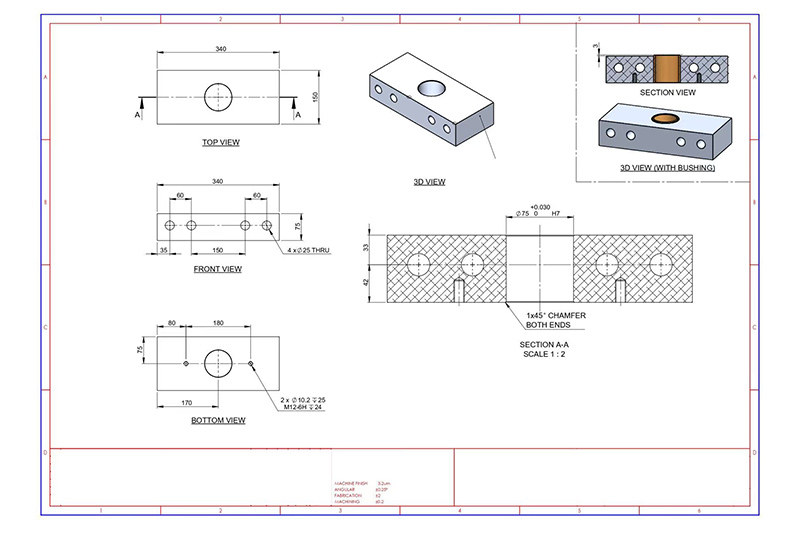
2. Orthographic & Auxiliary Views
- Primary Views: Show front, top, and side views.
- Section Views: Reveal internal features for clarity (e.g., hidden bores or grooves).
- Isometric/3D Sketches: Optional, for complex or visually confusing geometries.
3. Dimensions & Units
- Specify linear and angular dimensions clearly.
- Include hole sizes, radii, chamfers, and thread locations.
- State units clearly (mm or in) and maintain consistency across the drawing.
4. Tolerances
- General Tolerance Standards: Clauses like ISO 2768‑mK for non-critical dimensions.
- Feature-Specific Tolerances: Indicated per-feature, e.g., ±0.01 mm for bore diameter.
- GD&T Callouts: Include form, orientation, and positional controls (e.g., flatness, concentricity) where needed.
5. Surface Finish
- Use standard symbols (e.g., Ra ≤ 1.6 µm) to indicate surface roughness requirements.
- Apply finish requirements on critical functional or mating surfaces such as sealing faces or bearing journals.
6. Material & Treatments
- Specify base material (e.g., stainless steel 316L, Ti‑6Al‑4V).
- Include any required post-machining treatments: heat treatment, anodizing, plating, coating, or hardness specification.
7. Thread & Hole Features
- Clearly indicate thread size (e.g., M6×1, UNC ¼-20).
- Distinguish hole types: counterbore, countersink, tapped, through-hole.
- Call out depths and positional tolerances for each hole or feature.
8. Notes & Special Instructions
- Include instructions for deburring, laser engraving, assembly fit, or QA inspection.
- Place notes in a standardized section, clearly referenced to part features or notes identifiers.
- Specify any packaging, handling, or certification requirements (e.g., cleanroom shipping, barcoding, RoHS compliance).
Common Drawing Standards for CNC Machining
Standards ensure uniformity and clarity in machining drawings across industries and international borders. Whether you’re communicating with local or overseas suppliers, using the correct drafting standard helps eliminate confusion and machining errors.
Global CNC Drawing Standards Explained
| Standard | Region / Focus | Key Use |
|---|---|---|
| ASME Y14.5 | North America | Comprehensive guide to Geometric Dimensioning & Tolerancing (GD&T). It provides symbols and rules for specifying form, orientation, location, and runout of features. |
| ISO 2768 | Global / Europe | General tolerancing for dimensions that do not have individually assigned tolerances. Divided into tolerance classes like f (fine), m (medium), c (coarse), and v (very coarse). |
| DIN Standards | Germany / EU | Focus on threads (DIN 13), fits (DIN 7154-7158), and specific part drawings. Common in high-precision manufacturing and standardized hardware parts. |
| JIS Standards | Japan | Japanese Industrial Standards used widely in Asia. Includes drawing symbols, layout, and projection methods. Compatible with ISO in many cases but with local-specific notations. |
Choosing the Right Standard
If you’re working across borders, it’s vital to match the drawing standard with the regional expectation of your machining vendor. For instance, use ASME Y14.5 for U.S.-based manufacturers and ISO 2768 for European shops. If you’re designing for a global supply chain, include both the drawing standard reference and explanatory notes to align expectations.
Onlyindustries engineers are fluent in interpreting and applying all major global drafting standards. We can adapt your 3D CAD models and 2D drawings to ensure compliance with industry requirements and seamless manufacturer handoffs.
Best Practices for Creating Machining Drawings
Well-crafted machining drawings are more than just a visual blueprint—they are precision instructions that bridge the gap between design and manufacturing. Following best practices ensures clarity, reduces production errors, and facilitates quality control.
1.Avoid Over-Dimensioning
Cluttering your drawing with redundant or unnecessary dimensions can create confusion and conflicting instructions for machinists. Prioritize only the features that directly impact function or fit and trust standard tolerancing practices for the rest.
2.Use GD&T for Functional Requirements
Geometric Dimensioning and Tolerancing (GD&T) offers a powerful language for defining part geometry, such as flatness, roundness, and true position. Use it to clearly communicate how critical surfaces and features must behave relative to each other.
3. Clearly Define Datums
Datums serve as the anchor points for machining and inspection. Select stable and accessible surfaces to act as datums, and reference them consistently in your dimensioning strategy to eliminate guesswork during alignment and setup.

4.Design for Manufacturability (DFM)
Avoid overly tight tolerances or features like undercuts unless absolutely necessary. These can drive up costs and require specialty tooling. Stick to machining-friendly geometries that ensure consistency across production runs.
5.Highlight Critical Features
Use bold fonts, callouts, or section views to emphasize critical dimensions or tolerances. This alerts machinists and quality inspectors to features that must be controlled with high precision, such as sealing surfaces or thread fits.
6.Add a Revision Table
Track every change to your drawing by including a revision table. This prevents outdated versions from being used in production and helps maintain traceability during audits or customer reviews.
7.Ensure Consistent Units & Scale
Verify that the units (mm/inch) are specified and consistent throughout the drawing. Use appropriate scale settings so all dimensions are legible and accurately reflect real-world part size. Inconsistencies in units or scale are a common source of costly manufacturing mistakes.
At Onlyindustries, we regularly assist clients in revising or preparing production-ready machining drawings. We validate for GD&T accuracy, DFM compliance, and machining clarity before your designs go to the shop floor.
Why Machining Drawings Still Matter?
Even in today’s age of advanced 3D modeling and CAM automation, traditional 2D machining drawings remain indispensable. They deliver critical clarity and act as the standardized reference across engineering, production, and quality control teams.
Quality Control
Coordinate Measuring Machines (CMMs), optical comparators, and other inspection tools still rely on 2D dimensions and tolerances to verify part conformance. A precise drawing ensures that inspectors know what features matter most and what tolerances must be met.
Documentation & Compliance
Regulated industries like medical, aerospace, and defense require documented proof of design intent and manufacturing consistency. Machining drawings provide the traceable foundation needed for audits, certifications, and legal compliance.
Vendor Communication
Not every CNC shop has access to your 3D CAD software or understands your modeling conventions. A machining drawing offers a clear, universal format to communicate part specifications, surface finishes, tolerances, and assembly requirements across global supply chains.
Revision Control
Drawings are essential for tracking design changes. Including a revision block ensures everyone is using the latest version and that previous revisions are archived properly. This minimizes risk, rework, and miscommunication during production handoffs.
At Onlyindustries, we work with both model-based and drawing-centric workflows. But even when you send a perfect 3D model, we’ll often ask for a 2D drawing to guarantee inspection accuracy, programming reliability, and production repeatability.
CNC Drawing Checklist?
Even a well-designed part can fail in production if the machining drawing lacks clarity or completeness. This checklist ensures your drawings are shop-ready and meet both technical and practical requirements for CNC manufacturing.
Part Number, Material, and Units
Include a unique part number, clearly specified material (e.g., 6061-T6 Aluminum), and unit system (mm or inches). This prevents confusion when programming CNC machines or sourcing raw stock.
At Least Two Orthographic Views
Top and front views are typically required; add side or section views for clarity on features like hidden pockets or internal threads. An isometric view is also helpful for quick visual understanding.
All Critical Dimensions and Tolerances
Dimension only what’s functionally or inspection-critical. Avoid redundant measurements. Apply tolerances using either general notes or feature-specific callouts to communicate acceptable variations.
Surface Finish and Thread Details
Use proper symbols to indicate surface roughness, such as Ra ≤ 1.6 μm for bearing surfaces. Include thread specs like “M8 x 1.25 – 6H” or “UNC ¼-20” with depth and class of fit clearly noted.
GD&T or ISO Standard Noted
State the applicable standard (e.g., ASME Y14.5 or ISO 2768-mK) to guide interpretation. If using Geometric Dimensioning and Tolerancing (GD&T), define your datums and tolerance frames precisely.
Drawing Reviewed and Revision Tracked
Use a title block with designer/engineer names, approval sign-off, and a revision history. This ensures everyone uses the current version and that design changes are traceable over time.
At Onlyindustries, we perform a final review of every drawing before machining—even if it’s customer-supplied. This extra step helps catch errors early, minimize downstream risk, and deliver high-quality parts on time.
Common Mistakes to Avoid?
Even experienced engineers can overlook small details in machining drawings that lead to costly delays or rework. Avoid these common pitfalls to streamline your CNC manufacturing process and improve communication with your machining partner.
Undefined Units
Leaving out whether dimensions are in millimeters or inches creates ambiguity. CNC programmers may default to the wrong unit system, resulting in significant scale errors.
Missing Tolerances
Without tolerances, machinists must guess acceptable variation, which compromises precision and quality. Use general tolerances for non-critical features and specify tight ones only where necessary.
Inconsistent Thread or Hole Callouts
Mixing up thread standards (e.g., M6 vs. UNC ¼-20) or missing depth indications leads to wrong tool selections and part rejections. Always include depth, type, and class of fit.
No Edge or Burr Treatment Instructions
Sharp or burr-laden edges can pose safety and functionality issues. Use general notes such as “Break all sharp edges” or “Deburr all machined surfaces” to guide finishing steps.
Submitting Only a 3D Model
3D CAD files show shape but don’t communicate tolerances, threads, finishes, or inspection points. Always pair your model with a complete 2D drawing to eliminate interpretation gaps.
At Onlyindustries, we flag these issues early in the DFM review process—helping you avoid revisions, ensure part accuracy, and hit tight deadlines with confidence.
Conclusion
Precision parts start with precise communication—your machining drawing is that foundation.
A complete and well-structured machining drawing ensures that every manufacturing team member—from programmer to operator to inspector—works with the same expectations. It reduces interpretation errors, streamlines setup, and allows for consistent quality checks across the production cycle.
Why It Matters
- Reduces Risk: Clear dimensions and tolerances prevent costly rework.
- Improves Efficiency: Eliminates back-and-forth with suppliers.
- Enhances Compliance: Supports ISO and regulatory traceability.
At Onlyindustries, we understand that high-performance CNC parts begin at the drawing board. Our team is here to assist with drawing preparation, GD&T application, and manufacturability checks—so your design translates into a part that meets every expectation.
Need Help with Your CNC Drawing?
Misinterpreted dimensions or overlooked tolerances can derail your entire machining project.
If you’re uncertain whether your drawings are fully optimized for CNC manufacturing, you’re not alone. At Onlyindustries, we routinely support engineers, designers, and procurement specialists in refining their technical documentation. Whether you’re prepping a prototype or gearing up for high-volume production, our team applies ISO 13485 and ASME Y14.5 expertise to help align your specs with real-world manufacturability.
What We Offer
- Drawing Reviews: We check for clarity, consistency, and completeness across all drawing sections.
- GD&T Support: Our experts can suggest practical applications of datums, position tolerances, and profile controls.
- Material and Process Guidance: We match your design to appropriate CNC tools, materials, and treatments.
- Tolerance Analysis: Ensure that your fit and function goals align with production feasibility.
Great parts begin with great drawings—and we’re here to help you get them right.
Contact us today to schedule a technical review or receive a custom quote tailored to your next CNC machining project.