Skip to content
 Splined shafts are essential for high-precision torque transfer—but their design and machining are anything but simple.
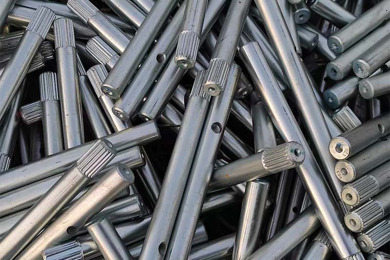
Splined shafts are cylindrical mechanical components with ridged teeth (splines) that transmit torque between connected parts. They’re used across aerospace, automotive, robotics, and industrial machinery applications, and demand tight tolerances and precision fitment for flawless operation.
In this guide, I’ll break down the different types of splines, machining methods, material options, design considerations, and quality control standards. Whether you’re a procurement manager or an R&D engineer, this is your go-to reference for sourcing or developing high-quality splined shafts.
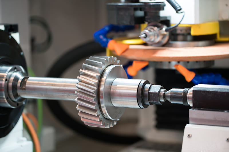
What Is a Splined Shaft?
Splined shafts solve a problem every mechanical engineer faces—how to transfer torque without slippage or backlash.
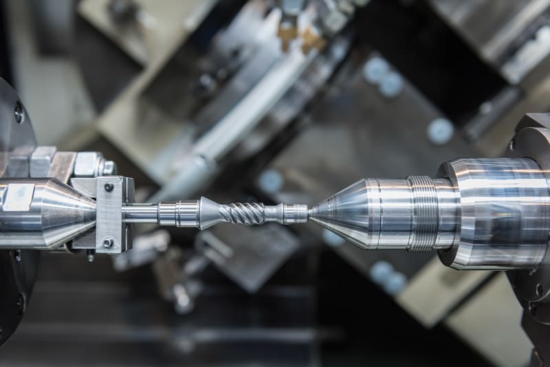
A splined shaft is a precision-machined cylindrical component with ridges or “teeth” that run parallel along its length. These splines interlock with matching grooves in a mating hub or gear, allowing the shaft to transmit rotational force with exact alignment and no slipping. This makes them critical in everything from steering systems to aircraft actuators.
Dive Deeper
What distinguishes a splined shaft from a keyed shaft? It’s the distributed load-bearing interface. Instead of a single key taking the brunt of the torque, splines spread that force across multiple teeth, increasing strength and wear resistance. This uniform load transfer also reduces the chance of fretting, galling, or tooth breakage under high loads or vibration.
Key attributes include:
- Angular Precision: Splines maintain fixed rotational relationships between components, essential for timing-critical systems.
- Axial Flexibility: Some splines—like sliding or ball splines—allow movement along the shaft while still transmitting torque.
- High Torque Capability: The multiple-tooth interface enables splines to carry more torque than single-key systems.
- Tight Tolerance Fit: Controlled runout and tooth engagement ensure concentric rotation, ideal for dynamic assemblies.
Splined shafts come in internal or external configurations and are available in a wide variety of forms to meet different load and motion requirements. From aerospace flight surfaces to automotive gearboxes, their role is central wherever torque and alignment need to coexist with absolute reliability.
What Are the Common Types of Splines?
Choosing the right spline isn’t just about fit—it’s about motion, load, and durability.
Splines come in several types, each engineered for specific performance characteristics. From the curved involute spline for automotive torque transmission to precision ball splines in robotics, your application should guide your choice.
Dive Deeper
Here’s a breakdown of the most widely used spline types and where they shine:
| Type | Description | Applications |
|---|---|---|
| Involute Spline | Curved tooth profiles distribute load uniformly and ensure accurate centering during rotation. | Automotive transmission shafts, aerospace control linkages |
| Straight-Sided Spline | Flat flanks make them easier to machine; suitable for static torque transmission but less forgiving under dynamic loads. | Industrial couplings, general-purpose machinery |
| Helical Spline | Twisted tooth orientation allows for smoother load transfer and axial movement—ideal for parts under compound motion. | Actuators, telescoping drives in aerospace and robotics |
| Crowned Spline | Tooth height is slightly varied (crowned) to tolerate minor misalignments and reduce edge-loading stress. | High-speed rotary shafts, dynamic couplings |
| Ball Spline | Incorporates recirculating ball tracks for torque transmission with linear motion—highly precise and low friction. | Robotic arms, precision linear drives |
| Internal vs External | External splines are cut on shafts; internal splines are machined into mating components like gears or hubs. | Used together in nearly all rotational torque transfer systems |
Each spline type involves unique tooling and inspection methods, so consult your machining partner early. At Onlyindustries, we guide our clients through design-to-production decisions—from spline form selection to heat treatment and fit class optimization.
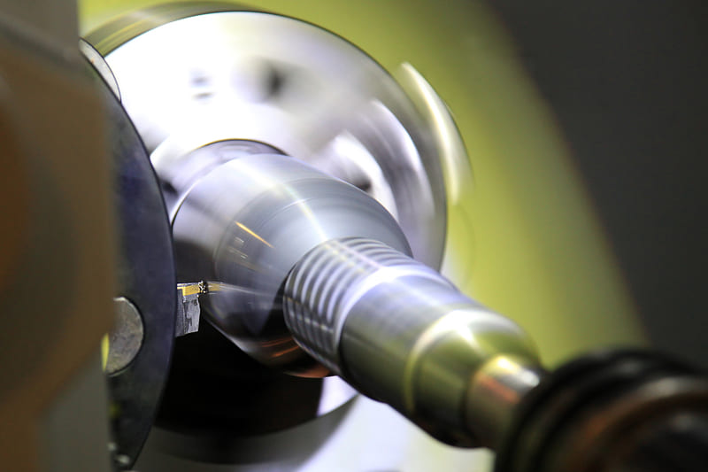
What Are the Main Splined Shaft Machining Methods?
Every machining method impacts cost, volume, and tolerance—choose wisely.
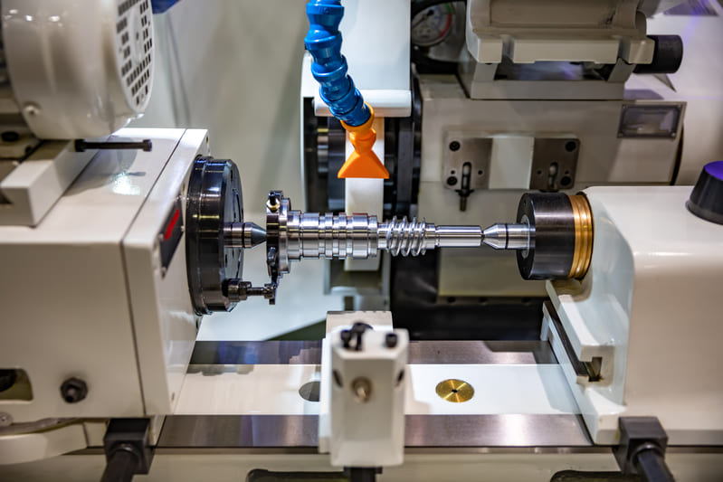
Splined shafts can be manufactured through various techniques, each with specific advantages depending on production volume, material type, and geometry complexity. From broaching to EDM, selecting the right method helps ensure both precision and production efficiency.
Dive Deeper
Here’s how the most common spline machining methods stack up:
| Method | How It Works | Ideal Use Case |
|---|---|---|
| Broaching | Uses a toothed tool that progressively removes material to cut internal splines in one stroke. | High-volume production of internal splines—e.g., transmission hubs |
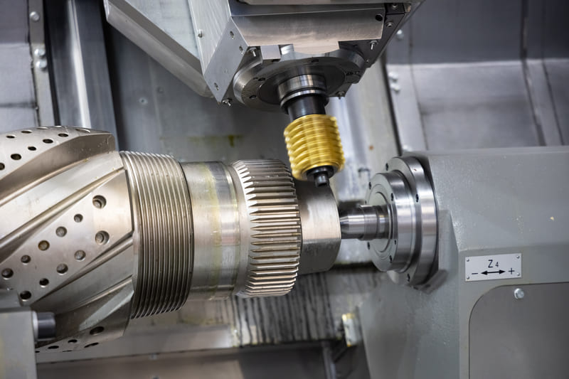
| Hobbing | A rotary cutter shapes external splines in a continuous process, often on a gear hobbing machine. | Automotive shafts and gear-like profiles with moderate volume needs |
| Shaping | Involves a reciprocating cutter to cut both internal and external splines. | Custom or low-volume splines, including blind-hole geometries |
| CNC Milling | Form tools or end mills cut spline profiles on a CNC machine, offering flexibility and fast setup changes. | Prototypes, low-volume parts, or varied spline geometries |
| Rolling (Cold Forming) | Deforms material plastically into spline shape using dies—no material is removed. | Mass production where fatigue resistance and cost savings are priorities |
| EDM (Electrical Discharge Machining) | Uses electrical discharges to erode precise spline geometry, especially in hard or delicate materials. | High-precision internal splines with tight tolerances in aerospace or medical sectors |
At Onlyindustries, we often recommend a hybrid approach—EDM or milling for prototyping, followed by broaching or rolling for scaled production. By aligning machining methods with your performance and cost targets, we ensure your splines meet spec and production goals.
What Materials Are Best for Splined Shafts?
Material choice is the foundation of strength, wear life, and machining cost.
Splined shafts must resist torsion, fatigue, wear, and—in many cases—corrosion. Selecting the right material ensures your shaft performs under stress while staying within budget and production constraints. Equally important: post-machining treatments like heat hardening that can transform base metals into performance-ready components.
Dive Deeper
Here’s a breakdown of the most common materials used for splined shafts and what they offer:
| Material | Key Characteristics | Best For |
|---|---|---|
| Alloy Steels (4140, 4340) | High tensile strength, good machinability, and excellent fatigue resistance. Can be surface hardened. | Automotive, aerospace, and industrial drive systems |
| Carbon Steel (1045) | Lower cost, decent strength, and easy to machine. Requires surface treatment for heavy loads or wear. | Moderate-duty splines in cost-sensitive applications |
| Stainless Steel (17-4PH, 316) | Corrosion-resistant and high strength (especially 17-4PH). May be harder to machine without proper tooling. | Medical, food processing, and marine splined components |
| Aluminum (7075) | Lightweight with good strength-to-weight ratio. Requires anodizing or coating for wear resistance. | Robotics, UAVs, and weight-critical platforms |
| Titanium (Grade 5, 6Al-4V) | Extreme strength, corrosion resistance, and light weight. Challenging to machine and expensive. | Aerospace, defense, and medical implants |
Heat Treatment & Surface Finishing
To boost fatigue life and surface durability, many shafts are treated post-machining:
- Induction Hardening: Increases surface hardness while keeping the core ductile.
- Carburizing: Adds a high-carbon outer layer for wear resistance.
- Black Oxide or Phosphate Coating: Adds corrosion resistance with minimal dimensional impact.
At Onlyindustries, we match material and heat treatment to your functional needs and volume targets. For aerospace customers, for instance, we’ve helped select 4340 with nitriding to achieve both strength and corrosion protection—without compromising inspectability or cost.
What Are the Tolerances and Surface Finish Standards for Splined Shafts?
In spline engineering, microns matter—poor tolerancing undermines fit, function, and longevity.
Tolerances and surface finishes directly influence how well splined shafts perform under load, fit into mating parts, and resist wear. Tight control ensures proper tooth engagement, smooth torque transmission, and minimal backlash—especially important in precision-critical systems like aerospace or robotics.
Dive Deeper
Here are the standard benchmarks for high-precision splined shaft production:
| Feature | Typical Tolerance | Why It Matters |
|---|---|---|
| Spline Tooth Width | ±0.01 mm to ±0.05 mm | Ensures proper fit with mating spline hub—prevents lash or tight interference |
| Runout (Radial/Total) | ≤ 0.01 mm | Maintains concentricity, reducing imbalance and uneven wear in rotating systems |
| Surface Finish (Tooth Flank) | Ra 0.8–1.6 µm | Supports smooth load engagement and lowers friction, heat, and wear |
Surface Treatment Options
Post-machining treatments improve surface hardness, corrosion resistance, and cosmetic appearance:
- Black Oxide: Minimal thickness; adds rust resistance for low-stress parts.
- Phosphate Coating: Good for wear resistance and lubricant retention.
- Hard Chrome Plating: Adds significant surface hardness and corrosion protection; ideal for aerospace and marine use.
At Onlyindustries, we validate all tolerances using precision metrology—from CMMs to digital profilometers. For high-rotation components, we’ve delivered spline shafts with Ra < 0.4 µm finish and runout within 5 microns—ensuring not just compliance, but competitive performance at scale.
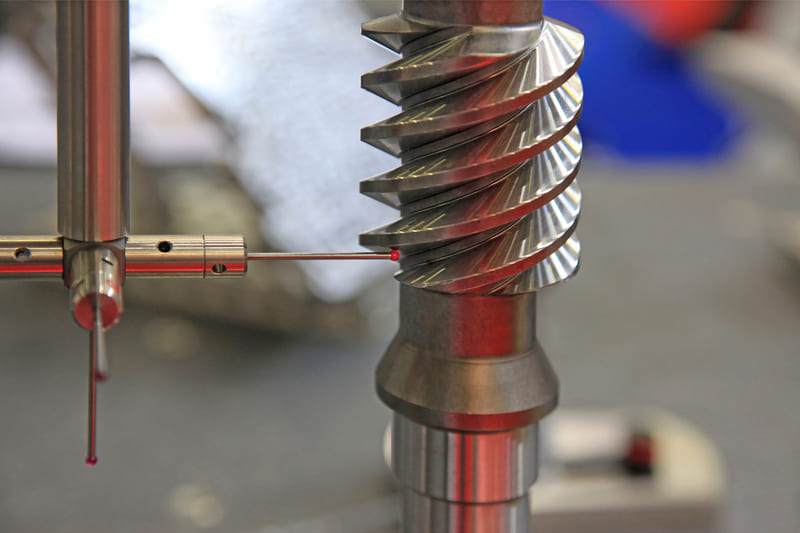
How Is Quality Control and Inspection Performed on Splined Shafts?
Precision without verification is just a guess—inspection confirms your spec is reality.
In splined shaft production, quality control isn’t an afterthought—it’s built into the process. Due to the tight tolerances and geometric complexity of splines, advanced metrology tools are required to inspect both external and internal profiles accurately. Reliable inspection ensures interchangeability, performance under load, and zero-fit issues on assembly lines.
Dive Deeper
At Onlyindustries, we implement multilayered inspection routines to ensure every splined shaft meets customer specs. Here’s what that looks like:
| Inspection Method | Purpose | Tools Used |
|---|---|---|
| Dimensional Verification | Confirm spline geometry—pitch, major/minor diameter, tooth width, spacing | CMM (Coordinate Measuring Machine), digital calipers, micrometers |
| Go/No-Go Fit Checks | Rapidly verify if spline falls within acceptable tolerance envelope | Spline gauges (Class 4–6 depending on fit) |
| Profile & Contour Inspection | Check for correct tooth shape and form deviation from CAD model | Profile projectors, toolmaker’s microscopes, optical comparators |
| Surface Finish Analysis | Evaluate Ra value for wear-prone tooth flanks and shaft body | Surface roughness testers (contact or non-contact) |
| Runout Measurement | Ensure shaft concentricity under rotation to prevent imbalance | Dial indicators, rotary test fixtures |
We also perform First Article Inspections (FAI) for every new batch or revision. These include detailed CMM reports, material traceability documents, and if needed, PPAP (Production Part Approval Process) packages for automotive-grade components.
For high-precision aerospace programs, we’ve developed spline inspection routines with tolerance validation down to ±0.005 mm, using multi-axis metrology systems calibrated to ISO/AS standards.
What Are the Common Applications of Splined Shafts?
Splined shafts are where motion meets muscle—used wherever rotational power and alignment are critical.
Across industries, splined shafts play a pivotal role in enabling torque transmission and synchronized motion between rotating components. Their adaptability to different torque loads, misalignment conditions, and environmental stresses makes them indispensable in both everyday machines and mission-critical systems.

Dive Deeper
| Industry | Typical Applications | Key Requirements |
|---|---|---|
| Automotive | Drivetrain shafts, steering columns, constant velocity joints | Mass manufacturability, vibration dampening, tight class 5–6 spline fits |
| Aerospace | Rotor drive shafts, aircraft control actuators | Lightweight alloys, micron-level tolerance, anti-fatigue surfacing |
| Industrial Equipment | Gearboxes, lifting systems, motor couplings | High torque capacity, surface-hardened profiles, long wear cycles |
| Robotics | Servo actuator outputs, joint axes, harmonic drives | Ultra-low backlash, smooth engagement, precise centering |
| Oil & Gas | Downhole drilling tools, hydraulic pumps | Extreme torque load, corrosion resistance, high-strength heat-treated steel |
| Marine | Propeller shafts, rudder control systems | Stainless or phosphate-coated steel, saltwater resistance, dynamic stability |
At Onlyindustries, we’ve manufactured splined shafts for EV transmissions that must endure 250,000+ km, and for satellite mechanisms requiring near-zero backlash. This application diversity underscores the value of tailored engineering—where the spline type, material, and process flow align with the demands of the real-world environment.
What Design Considerations Should Engineers Prioritize for Splined Shafts?
Designing a splined shaft isn’t just about geometry—it’s a balance of torque, tolerance, and manufacturability.
From torque transmission to fit tolerance and lifecycle wear, every design decision impacts part performance and production efficiency. For engineers, getting the spline profile right means factoring in load conditions, tolerance classes, and production scale from day one.
Dive Deeper
| Consideration | Design Insight |
|---|---|
| Load Type | Pure torque or torque + axial load? Use helical or ball splines when axial motion is needed. Involute splines distribute torque better under vibration or shock. |
| Spline Fit Class | Choose the right ISO/ANSI fit class. Class 4–5 for slip fits, Class 6–7 for press fits. Tighter fits reduce backlash but require tighter machining tolerances. |
| Keyway vs. Spline | Spline interfaces outperform keyways in torque load and concentricity. Use splines when strength, precision, or longevity is a priority. |
| Material & Heat Treatment | Pick materials based on torque and environment—4140 steel for durability, 17-4PH for corrosion resistance. Use induction hardening or nitriding for fatigue life. |
| Machining Method vs. Volume | CNC milling or shaping for low volumes or prototype flexibility; broaching or cold rolling for mass production cost efficiency and repeatability. |
| Prototype Flexibility | Start with CNC milling to iterate fit, profile, or form. Transition to hobbing or broaching once the design is locked for volume production. |
At Onlyindustries, we help engineers validate design decisions early—advising on spline form, material spec, heat treat cycles, and tolerance strategy. We even simulate press fit interactions in CAD to ensure spline engagement and durability. Our prototyping service lets you iterate spline geometry with fast-turn CNC runs before committing to tooling.
Conclusion
Precision spline machining is more than just cutting teeth—it’s about engineering a fit-for-purpose solution from end to end.
Splined shafts sit at the core of countless motion systems, where failure isn’t an option. From selecting the right spline form and material to choosing the most cost-effective machining method, success lies in the details. And with tight tolerances, load-specific geometries, and fit criticality, design and production must align seamlessly.
At Onlyindustries, we don’t just manufacture splines—we engineer them. Our process begins with collaborative design reviews, moves through exacting machining protocols, and finishes with industry-grade quality control. Whether you’re building automotive shafts by the thousand or fine-tuning an aerospace actuator prototype, we bring the same focus to accuracy, repeatability, and delivery confidence.
Need help defining spline specs or scaling production? Let’s turn your design intent into performance-grade reality.