Skip to content
 Casting is one of the oldest and most versatile manufacturing methods. It involves pouring molten material into a mold, where it solidifies to form the desired shape. From precision aerospace components to heavy-duty industrial machinery, casting processes vary widely in technique, material compatibility, and performance characteristics.
This guide explores 11 different casting processes—covering how they work, typical applications, advantages, and limitations—so you can choose the right method for your project.
Sand Casting
Sand casting is one of the oldest and most widely used metal casting processes, known for its versatility and cost-effectiveness, especially for large and heavy components. While the basic principle has remained unchanged for centuries, modern advancements in sand mixtures, binders, and pattern-making techniques have greatly improved quality and repeatability.
Sand casting works by creating a mold cavity in compacted sand, into which molten metal is poured. Once the metal solidifies, the sand mold is broken apart to retrieve the casting. This makes it a single-use mold process, but the sand can often be reclaimed and reused.
Why Sand Casting Remains Popular
Sand casting continues to dominate in applications where part size, weight, and material variety outweigh the need for ultra-fine surface finishes or tight tolerances. The ability to produce both small prototypes and massive industrial parts without prohibitive tooling costs makes it highly competitive.
Process Steps in Detail
| Step | Description |
|---|---|
| 1. Pattern Creation | A replica of the desired part, often made from wood, plastic, or metal, is prepared with allowances for shrinkage and machining. |
| 2. Mold Preparation | The pattern is placed in a molding box and packed with specially prepared sand (silica sand mixed with binders like clay or resin). |
| 3. Mold Assembly | The mold halves (cope and drag) are separated, the pattern is removed, and cores are placed if hollow sections are needed. |
| 4. Pouring | Molten metal is poured into the mold through a gating system designed for optimal flow and minimal defects. |
| 5. Cooling and Shakeout | After solidification, the mold is broken apart to remove the casting, and the sand is reclaimed. |
| 6. Cleaning and Finishing | Excess material from runners and risers is removed, and surface finishing or machining is performed as needed. |
Advantages of Sand Casting
- Low tooling and mold cost compared to permanent mold methods.
- Ability to handle extremely large parts (several tons in weight).
- Compatible with nearly all metals, including ferrous and non-ferrous alloys.
- Flexible for both low-volume and medium-volume production.
Limitations of Sand Casting
- Rougher surface finish compared to investment or die casting.
- Lower dimensional accuracy; may require post-machining.
- Slower production rate compared to high-pressure casting methods.
Applications
- Large engine blocks and cylinder heads.
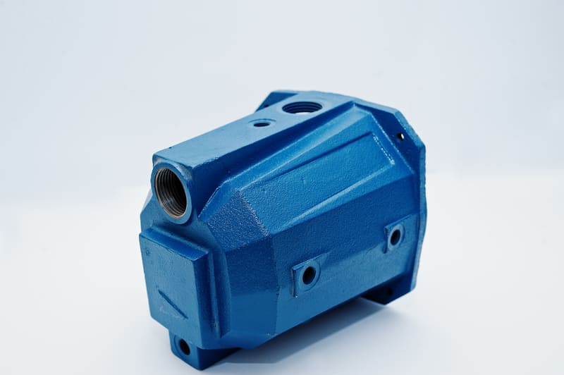
- Pump and valve housings for industrial use.
- Heavy-duty machine bases and frames.
- Custom architectural metalwork.
Pro Tip for Engineers
When designing for sand casting, ensure generous draft angles (1–3°) for easy pattern removal, and design gating systems that minimize turbulence to reduce defects like porosity or inclusions.
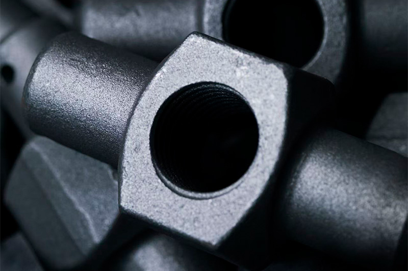
Investment Casting (Lost Wax Casting)
Investment casting, also known as lost wax casting, is a high-precision casting process capable of producing intricate shapes with exceptional surface quality. The name “investment” refers to the ceramic material that envelops the wax pattern, forming a highly detailed mold. This method is widely used in aerospace, medical, and jewelry industries, where complex geometry and accuracy are critical.
The process dates back thousands of years but has evolved with modern materials and automation, enabling the production of both small, delicate parts and complex industrial components with tight tolerances.
Why Choose Investment Casting
Investment casting is often selected when the component geometry is too complex for machining or other casting processes, and when excellent surface finish and dimensional accuracy are priorities. It eliminates or greatly reduces the need for secondary machining.
Process Steps in Detail
| Step | Description |
|---|---|
| 1. Wax Pattern Creation | A wax replica of the final part is made using an injection mold. Multiple patterns can be assembled onto a wax “tree” for batch processing. |
| 2. Shell Building | The wax pattern is repeatedly dipped in ceramic slurry and sprinkled with fine sand, then dried. This process is repeated until a strong ceramic shell forms. |
| 3. Wax Removal | The ceramic-coated pattern is placed in an autoclave or furnace to melt and drain the wax, leaving a hollow mold. |
| 4. Metal Pouring | Molten metal is poured into the preheated ceramic mold to fill the cavity completely. |
| 5. Cooling and Shell Removal | After solidification, the ceramic shell is broken away mechanically or via blasting. |
| 6. Finishing | Gates and sprues are removed, and the casting may undergo minimal machining or polishing. |
Advantages of Investment Casting
- Exceptional surface finish (Ra as low as 1.6–3.2 μm).
- High dimensional accuracy (tolerances up to ±0.1 mm possible).
- Can produce complex geometries with internal features and thin walls.
- Supports a wide range of metals, including superalloys, stainless steels, and titanium.
Limitations of Investment Casting
- Higher production cost compared to sand casting.
- Longer lead times due to multi-step process.
- Not ideal for very large parts due to mold fragility and cost.
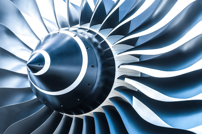
Applications
- Aerospace turbine blades and vanes.
- Orthopedic implants and surgical tools.
- High-precision automotive engine components.
- Complex jewelry designs with fine detail.
Pro Tip for Engineers
When designing for investment casting, maintain uniform wall thickness where possible to avoid differential cooling, and consult your foundry early to optimize gating and runner design for defect prevention.
Die Casting
Die casting is a high-speed, high-precision casting process that forces molten metal into a reusable steel mold—called a die—under high pressure. This method is widely used in automotive, electronics, and industrial manufacturing due to its ability to produce large volumes of complex, dimensionally accurate components with excellent surface finishes.
By combining precision tooling with rapid injection, die casting can deliver near-net-shape parts that require little or no post-machining, making it ideal for high-volume production runs.
Why Choose Die Casting
Die casting excels when you need consistent, detailed parts in large quantities. It is especially advantageous for producing thin-walled components with tight tolerances and smooth surfaces, reducing downstream finishing costs.
Process Steps in Detail
| Step | Description |
|---|---|
| 1. Mold Preparation | The steel dies are cleaned, lubricated, and clamped together to ensure accurate alignment and release. |
| 2. Metal Injection | Molten metal—commonly aluminum, zinc, or magnesium—is injected into the die cavity at high pressure (up to 1,500 bar) using a plunger system. |
| 3. Cooling & Solidification | The metal rapidly cools and solidifies inside the die, aided by cooling channels within the mold. |
| 4. Ejection | The die halves are separated, and ejector pins push the solidified casting out. |
| 5. Trimming & Finishing | Excess metal from runners and gates is trimmed away, and minor finishing operations may be performed. |
Advantages of Die Casting
- Excellent dimensional accuracy (tolerances up to ±0.05 mm possible).
- High production rate—thousands of identical parts per day.
- Superior surface finish (Ra as low as 1.6–3.2 μm).
- Ability to cast complex shapes with thin walls and fine features.
Limitations of Die Casting
- High initial tooling cost for die manufacturing.
- Best suited for non-ferrous metals with lower melting points (e.g., aluminum, zinc, magnesium).
- Not cost-effective for low production volumes.
Applications
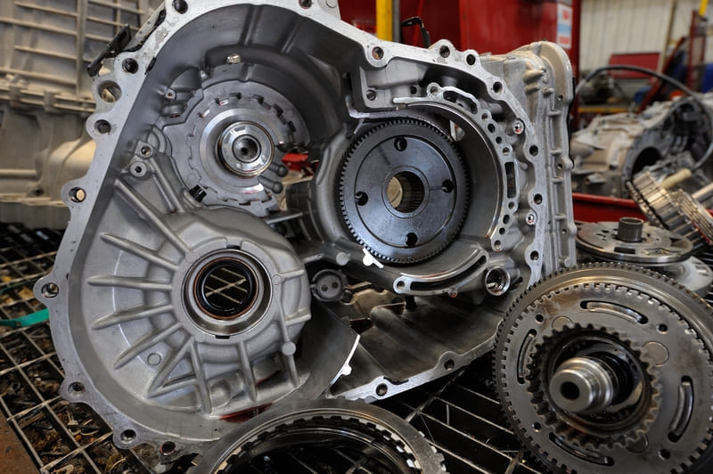
- Automotive engine housings, gearboxes, and structural parts.
- Consumer electronics casings and heat sinks.
- Industrial pump housings and brackets.
- Appliance components requiring both strength and aesthetics.
Pro Tip for Engineers
Incorporate uniform wall thickness and generous radii into your die casting designs to improve metal flow, reduce stress concentrations, and extend die life. Engage your foundry early to optimize part geometry for manufacturability and cost.
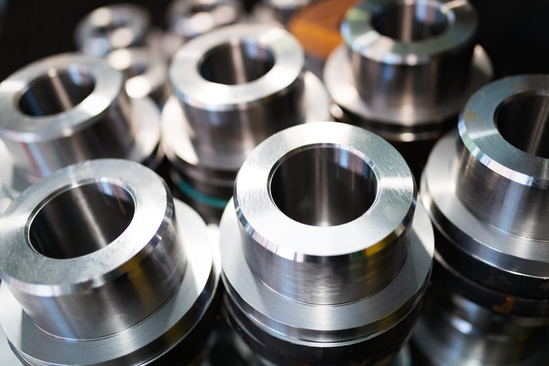
Centrifugal Casting
Centrifugal casting is a specialized metal casting process where molten metal is poured into a rotating mold, and centrifugal force distributes it evenly against the mold walls. This method is especially effective for producing high-density, defect-free cylindrical or tubular components with excellent mechanical properties.
By eliminating reliance on gravity alone, centrifugal casting minimizes impurities and gas porosity, making it ideal for high-strength applications in industries such as aerospace, automotive, and energy.
Why Choose Centrifugal Casting
This process is the go-to choice when uniform wall thickness, high material integrity, and superior metallurgical quality are critical. It is particularly beneficial for parts that must withstand high pressures or rotational stresses.
Process Steps in Detail
| Step | Description |
|---|---|
| 1. Mold Preparation | The mold—usually made of steel or graphite—is preheated and coated with a refractory lining to protect against wear and ensure smooth surface finish. |
| 2. Mold Rotation | The mold begins rotating at high speed, generating centrifugal force proportional to the rotational velocity. |
| 3. Metal Pouring | Molten metal is introduced into the spinning mold. Centrifugal force pushes the metal outward, forming a uniform layer along the mold wall. |
| 4. Solidification | As the metal cools, impurities and lighter inclusions migrate toward the center, where they can be machined away. |
| 5. Ejection & Finishing | The finished casting is removed from the mold and undergoes any necessary machining or surface treatment. |
Advantages of Centrifugal Casting
- High-density castings with minimal porosity.
- Superior mechanical properties and grain structure.
- Excellent for cylindrical parts without requiring cores.
- Capability to produce large parts with thick or thin walls.
Limitations of Centrifugal Casting
- Limited to symmetrical, axis-centered shapes (e.g., tubes, rings, bushings).
- Requires specialized, high-speed rotating equipment.
- Center bore and inner surfaces often require post-machining.
Applications
- Pipes and tubing for high-pressure applications.
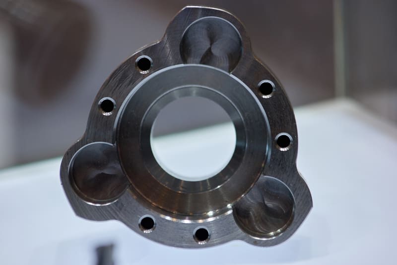
- Engine cylinder liners and sleeves.
- Industrial rollers and bushings.
- Aerospace turbine rings and energy sector components.
Pro Tip for Engineers
When designing for centrifugal casting, specify extra stock allowance on the inner diameter to account for impurity concentration at the center—this will ensure final machining yields a flawless surface and optimal performance.
Shell Molding
Shell molding is a precision casting process that uses resin-coated sand to form thin, hard-walled molds. This method is widely appreciated for producing dimensionally accurate and smooth-surfaced castings, especially in small to medium sizes. The process offers a balance between the versatility of sand casting and the precision of investment casting.
By creating a hardened shell mold that can withstand higher pouring temperatures and produce finer details, shell molding is ideal for components where both performance and aesthetics matter.
Why Choose Shell Molding
Shell molding is preferred when tighter tolerances and better surface finishes are required compared to traditional green sand casting. It offers reduced machining needs, faster mold setup, and higher repeatability—making it suitable for medium- to high-volume production runs.
Process Steps in Detail
| Step | Description |
|---|---|
| 1. Pattern Preparation | A metal pattern, usually made from steel or iron, is heated to a specific temperature to aid in resin curing. |
| 2. Sand Application | Fine silica sand coated with thermosetting resin is poured or blown over the heated pattern, forming an initial thin layer. |
| 3. Shell Formation | The resin-coated sand cures upon contact with the hot pattern, forming a solidified shell. The process is repeated to build the required shell thickness. |
| 4. Mold Assembly | The two mold halves are stripped from the pattern, assembled, and clamped together, ready for pouring. |
| 5. Pouring & Cooling | Molten metal is poured into the mold cavity, allowed to solidify, and the shell is broken away to retrieve the casting. |
Advantages of Shell Molding
- Produces castings with superior surface finish (Ra 3.2–6.3 μm).
- Good dimensional accuracy (±0.5 mm per 100 mm).
- Lower machining allowance compared to sand casting.
- Efficient for small-to-medium size production runs.
- Capable of producing thin-walled and complex shapes.
Limitations of Shell Molding
- Higher tooling costs compared to green sand casting.
- Not ideal for very large castings due to mold handling constraints.
- Pattern heating equipment and process control add to initial setup cost.
Applications
- Gear housings and pump bodies.
- Engine brackets and intake manifolds.
- Valve bodies and fittings.
- Small aerospace and defense components requiring precision.
Pro Tip for Engineers
For optimal results, specify shell molding when your design demands a high-quality surface finish and dimensional consistency but doesn’t justify the cost of investment casting. Proper gating and venting in shell molds will further reduce the risk of defects.
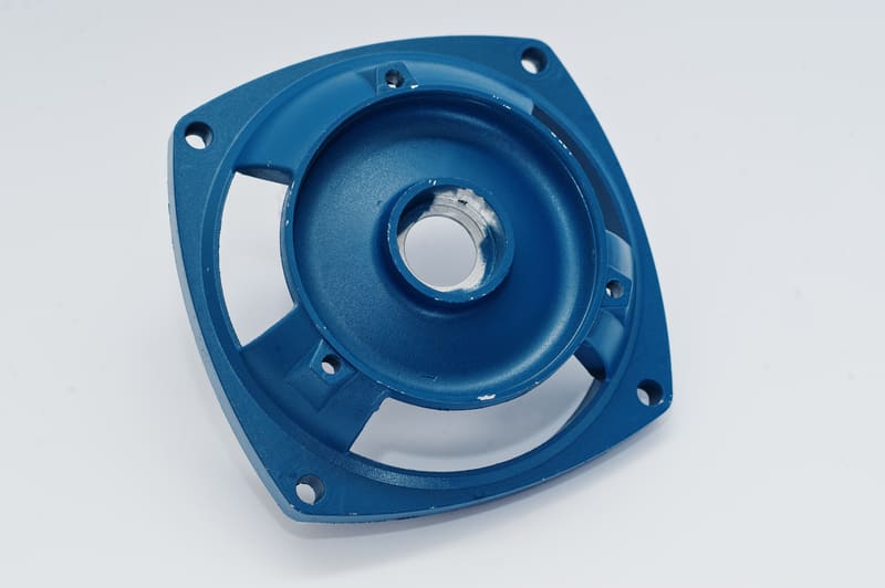
Permanent Mold Casting
Permanent mold casting is a precision casting process that uses reusable metal molds—typically made of cast iron, steel, or graphite—to produce parts with superior surface finish, dimensional accuracy, and repeatability. Unlike sand or plaster molds, which are destroyed after a single use, permanent molds are designed for multiple casting cycles, making them cost-effective for medium- to high-volume production runs.
This process relies on gravity or low pressure to fill the mold cavity with molten metal, producing strong and consistent castings with minimal defects.
Why Choose Permanent Mold Casting
Permanent mold casting is ideal for applications where consistent part quality, excellent mechanical properties, and smoother surfaces are required. Because the mold is metallic and reusable, it cools the molten metal faster, resulting in a finer grain structure and improved strength compared to sand casting.
Process Steps in Detail
| Step | Description |
|---|---|
| 1. Mold Preparation | The metal mold is preheated and coated with a refractory or graphite-based coating to prevent sticking and prolong mold life. |
| 2. Assembly | The mold halves are aligned and clamped together to ensure proper cavity formation. |
| 3. Pouring | Molten metal is poured into the mold cavity, typically using gravity. Low-pressure or tilt pouring can be used for more complex parts. |
| 4. Solidification | The mold material conducts heat away quickly, solidifying the casting faster and improving grain structure. |
| 5. Ejection | The mold is opened, and the solidified casting is ejected using ejector pins or manual removal. |
| 6. Cleaning | The casting is trimmed, cleaned, and finished as required before the mold is prepared for the next cycle. |
Advantages of Permanent Mold Casting
- Excellent surface finish (Ra 1.6–6.3 μm) with minimal post-processing.
- Higher mechanical strength due to faster cooling and fine grain structure.
- High dimensional accuracy and repeatability across production batches.
- Reusable mold reduces long-term tooling costs for high production volumes.
- Capable of producing complex shapes with cores.
Limitations of Permanent Mold Casting
- High initial mold manufacturing cost compared to expendable mold processes.
- Limited to lower-melting-point metals such as aluminum, magnesium, zinc, and some copper alloys.
- Mold size is restricted by equipment capacity and handling constraints.
Applications
- Automotive pistons and cylinder heads.
- Gear blanks and bearing housings.
- Aerospace structural components.
- Marine hardware and propellers.
- Industrial pump and compressor parts.
Pro Tip for Engineers
Permanent mold casting is best for parts where strength, surface finish, and dimensional accuracy are priorities, and production volumes justify the mold investment. For more complex geometries, consider adding sand or metal cores to achieve internal cavities without sacrificing surface quality.
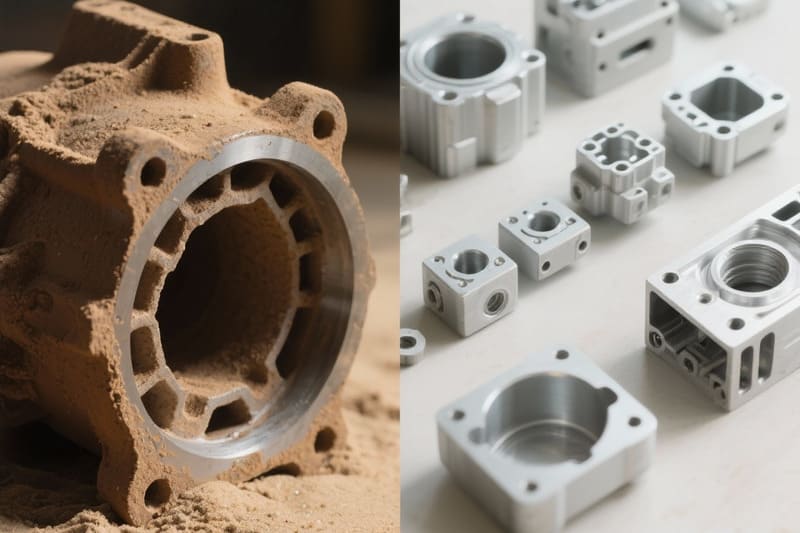
Lost Foam Casting
Lost foam casting is a near-net-shape casting process that uses a foam pattern to create complex metal components with minimal machining. The foam pattern—made from expanded polystyrene (EPS) or similar material—is coated with a refractory layer, placed in unbonded sand, and then replaced by molten metal as the foam vaporizes. This makes it ideal for producing intricate parts without the need for cores or extensive tooling modifications.
Why Choose Lost Foam Casting
Lost foam casting allows manufacturers to produce complex, single-piece castings that would otherwise require multiple components to be welded or bolted together. Since the foam evaporates completely during pouring, internal passages, curved surfaces, and undercuts can be incorporated directly into the casting without complex core setups.
Process Steps in Detail
| Step | Description |
|---|---|
| 1. Pattern Creation | The part shape is created using a foam pattern, often molded or CNC-machined from EPS blocks. |
| 2. Pattern Assembly | Multiple foam sections can be glued together to form large or complex geometries. |
| 3. Coating | The foam pattern is dipped or sprayed with a refractory coating to improve surface finish and control permeability. |
| 4. Mold Preparation | The coated foam is placed in a flask and surrounded by loose, unbonded sand, which is compacted for support. |
| 5. Pouring | Molten metal is poured into the pattern; the foam vaporizes and is replaced by the metal. |
| 6. Cooling and Shakeout | Once solidified, the casting is removed from the sand and cleaned of any residual coating. |
Advantages of Lost Foam Casting
- Allows highly complex shapes with no need for cores.
- Good dimensional accuracy with minimal machining required.
- Single-piece castings reduce assembly time and potential leak paths.
- Capable of producing thin-walled and lightweight structures.
- Flexible for low- to medium-volume production runs.
Limitations of Lost Foam Casting
- Surface finish (Ra ~6.3–12.5 μm) may require post-processing for critical applications.
- Foam patterns can be fragile and require careful handling.
- Pattern production cost can be high for very large parts.
- Gas control during pouring is crucial to avoid defects.
Applications
- Automotive engine blocks and cylinder heads.
- Industrial pump and compressor housings.
- Aerospace structural castings.
- Construction and agricultural machinery parts.
- Complex gearboxes and transmission casings.
Pro Tip for Engineers
For best results in lost foam casting, design parts with consistent wall thickness and proper venting channels in the foam pattern. This ensures smooth metal flow, prevents cold shuts, and minimizes trapped gases during pouring.
Plaster Mold Casting
Plaster mold casting is a precision casting process that uses a gypsum-based mold to achieve fine surface finishes and detailed features, especially for non-ferrous metals with low melting points. It is often chosen for prototype production, decorative applications, and parts requiring thin sections and high dimensional accuracy.
Why Choose Plaster Mold Casting
This method is ideal for producing small to medium-sized components where surface quality and detail are more important than production speed. The plaster mold’s smooth surface replicates fine details from the pattern, making it suitable for parts that require minimal post-processing or machining.
Process Steps in Detail
| Step | Description |
|---|---|
| 1. Pattern Creation | A pattern—often made of metal, wax, or plastic—is created to the exact shape of the desired casting. |
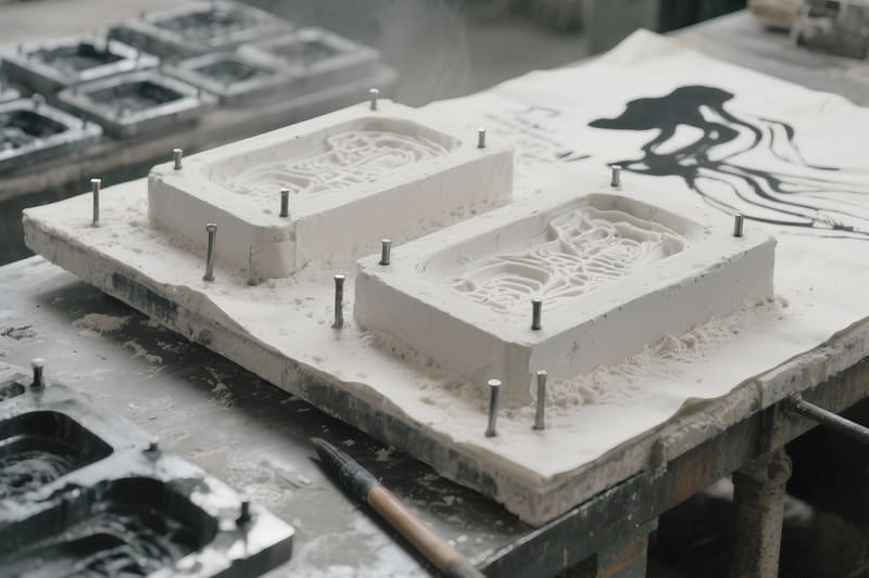
| 2. Mold Preparation | Gypsum plaster is mixed with water and additives, then poured over the pattern in a molding box. |
| 3. Mold Setting | The plaster hardens around the pattern, capturing fine details and textures. |
| 4. Pattern Removal | The pattern is carefully removed once the plaster mold is set. |
| 5. Mold Drying & Firing | The mold is dried and sometimes baked to remove residual moisture, preventing steam-related defects. |
| 6. Metal Pouring | Molten non-ferrous metal (aluminum, magnesium, copper alloys) is poured into the plaster mold. |
| 7. Cooling & Shakeout | After cooling, the plaster mold is broken away to retrieve the casting. |
Advantages of Plaster Mold Casting
- Excellent surface finish (Ra ~1.6–3.2 μm).
- High dimensional accuracy with minimal machining needed.
- Ability to produce thin-walled sections (as low as 1.5 mm).
- Reproduces intricate patterns and fine details.
- Good for short-run production and prototyping.
Limitations of Plaster Mold Casting
- Not suitable for ferrous metals or high-melting-point alloys.
- Lower mold strength compared to sand or ceramic molds.
- Slower production rate due to mold preparation and drying.
- Limited mold reusability—single-use molds only.
Applications
- Decorative hardware and fixtures.
- Prototype engine components.
- Thin-walled aerospace housings.
- Medical device components.
- Precision instrumentation parts.
Pro Tip for Engineers
When using plaster mold casting, ensure thorough mold drying before pouring metal to avoid steam explosions. For critical tolerances, consider pattern shrinkage allowances and mold expansion during firing.
Vacuum Casting (V-Process)
Vacuum casting, also known as the V-process, is a molding method that uses a vacuum to hold unbonded, dry sand in place around a pattern covered with a thin plastic film. This technique eliminates the need for binders or water, resulting in high-quality castings with smooth surfaces and precise dimensions.
Why Choose Vacuum Casting (V-Process)
The V-process is ideal for producing large, thin-walled, or intricate aluminum castings where surface quality and dimensional accuracy are critical. Because the sand is unbonded, it can be reused repeatedly, making the process environmentally friendly and cost-effective in the long term.
Process Steps in Detail
| Step | Description |
|---|---|
| 1. Pattern Preparation | A heat-resistant plastic film is placed over a metal pattern, which has tiny vacuum holes to hold the film tightly against the surface. |
| 2. Pattern Box Filling | The pattern box is filled with fine, dry, unbonded sand while a vacuum is applied to keep the film tight. |
| 3. Mold Formation | The sand is leveled and compacted, and another plastic film is placed on the back of the mold. Vacuum is applied to the mold halves to maintain shape. |
| 4. Mold Assembly | The cope and drag (top and bottom halves) are brought together while the vacuum is maintained. |
| 5. Metal Pouring | Molten metal (typically aluminum or magnesium) is poured into the cavity while the vacuum holds the mold stable. |
| 6. Cooling & Shakeout | Once the casting cools, the vacuum is released, and the unbonded sand falls away easily for recycling. |
Advantages of Vacuum Casting (V-Process)
- Excellent surface finish (Ra as low as 3.2 μm).
- No binders or additives in sand, making it recyclable and eco-friendly.
- High dimensional accuracy, reducing machining requirements.
- Suitable for large and thin-walled castings.
- Minimal mold wear and consistent quality over multiple cycles.
Limitations of Vacuum Casting (V-Process)
- Requires specialized vacuum equipment and patterns.
- Slower cycle time compared to high-pressure casting methods.
- Limited to non-ferrous metals and lower-melting-point alloys.
- Not ideal for very high-volume production.
Applications
- Automotive body panels and structural components.
- Aerospace housing and covers.
- Architectural aluminum panels.
- Large, thin-walled industrial enclosures.
- Marine aluminum castings.
Pro Tip for Engineers
When designing for the V-process, take advantage of the smooth surface finish and consistent mold accuracy to reduce post-processing costs. Ensure proper venting in the pattern design to allow complete metal flow during pouring.
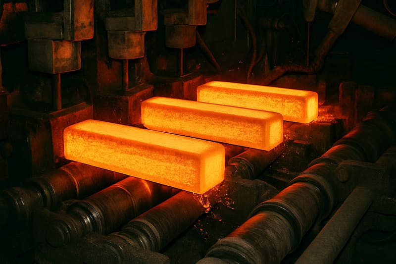
Continuous Casting
Continuous casting is a high-efficiency metal production process in which molten metal is solidified into a continuous strand and then cut into specific lengths. This process is widely used in the steel, aluminum, and copper industries to produce billets, blooms, slabs, and other semi-finished shapes with consistent quality.
Why Choose Continuous Casting
Continuous casting is ideal for high-volume manufacturing where uniform quality, reduced waste, and lower production costs are critical. By eliminating the need for ingot casting and subsequent reheating, the process increases productivity while minimizing energy consumption and material losses.
Process Steps in Detail
| Step | Description |
|---|---|
| 1. Ladle to Tundish Transfer | Molten metal from the ladle is poured into a tundish, which serves as a reservoir to feed the mold continuously and evenly. |
| 2. Mold Entry | The metal flows into a water-cooled copper mold, which initiates solidification while maintaining the desired cross-sectional shape. |
| 3. Strand Formation | The partially solidified strand exits the mold and is supported by rollers to prevent deformation. |
| 4. Secondary Cooling | Water sprays or mist cool the strand further until the metal is fully solidified. |
| 5. Straightening & Withdrawal | The strand is straightened, continuously pulled, and guided toward the cutting area. |
| 6. Cutting to Length | Oxy-fuel torches or mechanical shears cut the continuous strand into slabs, blooms, or billets according to customer specifications. |
Advantages of Continuous Casting
- Very high production rate with consistent quality.
- Reduces energy costs by eliminating reheating between casting and rolling stages.
- Produces near-net-shape products, minimizing machining waste.
- Improved metal quality with fewer internal defects compared to ingot casting.
- Continuous operation supports large-scale manufacturing.
Limitations of Continuous Casting
- High initial equipment and setup costs.
- Limited flexibility—each machine is optimized for specific shapes and sizes.
- Requires precise temperature and flow control for defect-free results.
- Not suitable for small-batch or highly customized shapes.
Applications
- Steel industry: slabs for plate rolling, blooms for structural steel, billets for rebar and wire rod production.
- Aluminum production: continuous ingots for extrusion and rolling mills.
- Copper industry: continuous billets for electrical wiring and tubing.
- High-volume non-ferrous metal production for automotive and aerospace raw materials.
Pro Tip for Engineers
When specifying materials from continuous casting, consider downstream processes like rolling, forging, or extrusion. Optimize cross-sectional shapes to reduce secondary machining and improve overall cost efficiency.
Squeeze Casting
Squeeze casting, also known as liquid metal forging, is a hybrid process that combines the benefits of casting and forging. In this method, molten metal is poured into a preheated die, and then a hydraulic press applies high pressure during solidification. This eliminates porosity, refines the grain structure, and significantly enhances the mechanical properties of the final part.
Why Choose Squeeze Casting
This process is ideal for producing high-strength, high-integrity components where traditional casting may leave internal defects. The high pressure ensures the molten metal completely fills the mold, creating dense, near-net-shape parts with minimal shrinkage. It’s particularly valued in industries requiring lightweight yet strong components, such as aerospace and automotive.
Process Steps in Detail
| Step | Description |
|---|---|
| 1. Die Preparation | The steel die is preheated to prevent thermal shock and improve metal flow. |
| 2. Molten Metal Pouring | Pre-measured molten metal is poured directly into the lower die cavity. |
| 3. Hydraulic Pressing | The upper die closes and applies high pressure (typically 50–150 MPa) during solidification. |
| 4. Solidification | Pressure is maintained until the casting fully solidifies, ensuring dense, defect-free structure. |
| 5. Ejection & Finishing | The die opens, and the part is ejected for minimal post-processing. |
Advantages of Squeeze Casting
- Produces high-strength, fine-grain parts comparable to forged components.
- Minimal porosity, shrinkage, and internal defects.
- Near-net-shape production reduces machining time and waste.
- Excellent mechanical properties, even in lightweight alloys like aluminum and magnesium.
- Improved wear and fatigue resistance.
Limitations of Squeeze Casting
- High capital investment in hydraulic presses and tooling.
- Lower production rate compared to high-pressure die casting.
- Requires precise control of pouring temperature and press timing.
- Limited suitability for very large parts due to press size constraints.
Applications
- Automotive: suspension arms, brake calipers, steering knuckles, and engine mounts.
- Aerospace: structural brackets, landing gear components, and high-load fittings.
- Industrial machinery: high-stress gears, pump housings, and hydraulic components.
- Defense: lightweight yet durable armor and weapon system parts.
Pro Tip for Engineers
When designing for squeeze casting, use smooth transitions and fillets to encourage complete metal flow under pressure. Specify alloys with high fluidity and good mechanical response to pressure solidification to maximize the process benefits.
Casting Process Comparison
Choosing the right casting process requires balancing cost, precision, surface finish, and production volume. Each method has unique strengths and trade-offs, and understanding these differences helps engineers and buyers match manufacturing methods to specific design requirements.
Detailed Process Evaluation
| Casting Method | Accuracy | Surface Finish | Production Rate | Cost | Suitable Metals | Best Use Cases |
|---|---|---|---|---|---|---|
| Sand Casting | Low–Medium | Rough | Low–Medium | Low | All | Large parts, low-volume runs, cost-sensitive projects |
| Investment Casting | High | Excellent | Low | High | All | Complex geometries, high accuracy, aerospace/medical |
| Die Casting | High | Excellent | High | High | Non-ferrous | High-volume aluminum, zinc, magnesium parts |
| Centrifugal Casting | High | Good | Medium | Medium | All | Pipes, bushings, high-integrity cylindrical parts |
| Shell Molding | Medium–High | Good | Medium | Medium | All | Small/medium precision parts, repeatable production |
| Permanent Mold Casting | High | Good | Medium–High | High | Non-ferrous | Medium-volume aluminum/magnesium parts |
| Lost Foam Casting | Medium–High | Medium | Medium | Medium | All | Complex internal geometries, automotive blocks |
| Plaster Mold Casting | High | Excellent | Low | Medium | Non-ferrous | Prototypes, decorative parts, thin-walled components |
| Vacuum Casting (V-Process) | High | Good | Low–Medium | Medium | All | Large, thin-walled aluminum components |
| Continuous Casting | High | Good | Very High | High | All | Long metal sections: billets, blooms, slabs |
| Squeeze Casting | High | Excellent | Low | High | Non-ferrous | High-strength automotive/aerospace parts |
Key Insights for Process Selection
- For high-complexity, high-accuracy parts – Investment casting and die casting lead the pack, offering tight tolerances and excellent finishes.
- For large, low-volume parts – Sand casting and lost foam casting provide cost-effectiveness and design flexibility.
- For high-strength, dense parts – Squeeze casting and centrifugal casting deliver superior mechanical performance.
- For continuous production of stock shapes – Continuous casting ensures efficiency and consistent metallurgical quality.
Pro Tip
When comparing casting processes, factor in not just per-unit cost, but also tooling investment, post-processing needs, and quality control requirements. A slightly higher process cost can often pay for itself through reduced machining, less scrap, and improved performance.
Final Thoughts
Choosing the right casting process is not a one-size-fits-all decision — it’s a strategic balance between part geometry, material type, production volume, cost targets, and performance requirements. Selecting incorrectly can lead to excess machining, structural weaknesses, or unnecessary expenses.
Why Process Selection Matters
Each casting process comes with distinct trade-offs in terms of precision, surface finish, tooling cost, and production speed. For example, investment casting may provide exceptional accuracy and finish but might be overkill for a large, low-precision industrial housing that could be made far more economically with sand casting. Conversely, choosing sand casting for a critical aerospace turbine blade would compromise safety and performance.
Decision-Making Checklist
- Geometry Complexity – Does the design have intricate internal cavities or thin walls?
- Material Requirements – Are you working with ferrous, non-ferrous, or high-temperature alloys?
- Production Volume – Is this a prototype run, a medium batch, or high-volume mass production?
- Mechanical Properties – Does the part require high strength, wear resistance, or low porosity?
- Finish & Tolerance – How critical is surface smoothness and dimensional accuracy?
- Tooling Budget – Is a higher upfront cost acceptable if it lowers per-unit cost later?
Practical Recommendations
If your project demands complex, high-accuracy shapes, lean toward investment casting or die casting. If you’re producing large, low-volume parts, sand casting or lost foam casting may be the most cost-effective. For high-strength structural applications, squeeze casting or centrifugal casting often deliver superior results. Always involve your manufacturing partner early — their experience can help balance design ambition with production realities.
Pro Tip
Never underestimate the value of prototyping. Running a small batch using a lower-cost casting method before committing to expensive tooling can validate design, detect flaws, and prevent costly rework down the line.